Changeover weeks are when a hydroponic system drain down is either a two-hour job or a two-day one. The difference is rarely the cleaning product. It is whether the design left a way for water to leave every part of the system: channels, manifolds, mains, tank and filter housings. Systems built without that route get cleaned by hand, section by section, and the sections nobody can reach simply do not get cleaned.
This is a design topic, not a cleaning procedure. Sanitiser choice and contact time belong to the cleaning and sanitizing cycle, and floor falls and gullies belong to site drainage. What follows is the part in between: making the system itself drainable and flushable.
Hydroponic System Drain Down: What “Drained” Actually Means
A system is drained when every section can be emptied to its lowest point without dismantling pipework, and when the water that comes out has somewhere legitimate to go. Emptying the tank is not draining the system; the tank is usually the easiest part.
The sections that decide whether the job is quick are at the ends of runs: channel outlets, manifold ends, lateral ends, filter bowls and any low loop in a main. Each is a place where water sits by design unless someone provided a way out.
Two definitions are worth writing into the specification so tenders are comparable:
- Drain-down: the system can be emptied by gravity through fixed valves to its low points, within a stated time.
- Flush point: a valved opening sized to pass debris, at an end or low point, discharging to a known destination.
Without those definitions in writing, a quotation listing “drain valves” may mean one valve at the tank and nothing else.
Finding the Low Points Before the Pipe Is Fixed
Low points should be marked on the layout drawing, not discovered during the first clean-out. Walk the drawing in the order the water travels:
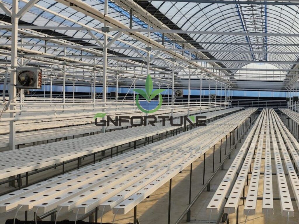
- Channel ends: every run has a low end by virtue of its working slope, and that end needs an outlet that opens.
- Manifold ends: a dead leg in operation and a sump when the zone closes.
- Mains: anywhere a main dips below its gradient, including under doorways.
- Filter and dosing bodies: bowls, strainers and injectors hold volume and sit low.
- Tank suction and return lines: often the longest un-drainable section on site.
Each marked low point gets a decision: a drain valve, a removable cap, or an acceptance that the section will be emptied another way. The third option should be rare and written down, because it becomes a standing task.
Drain-Down Slope and the Sections That Hold Water
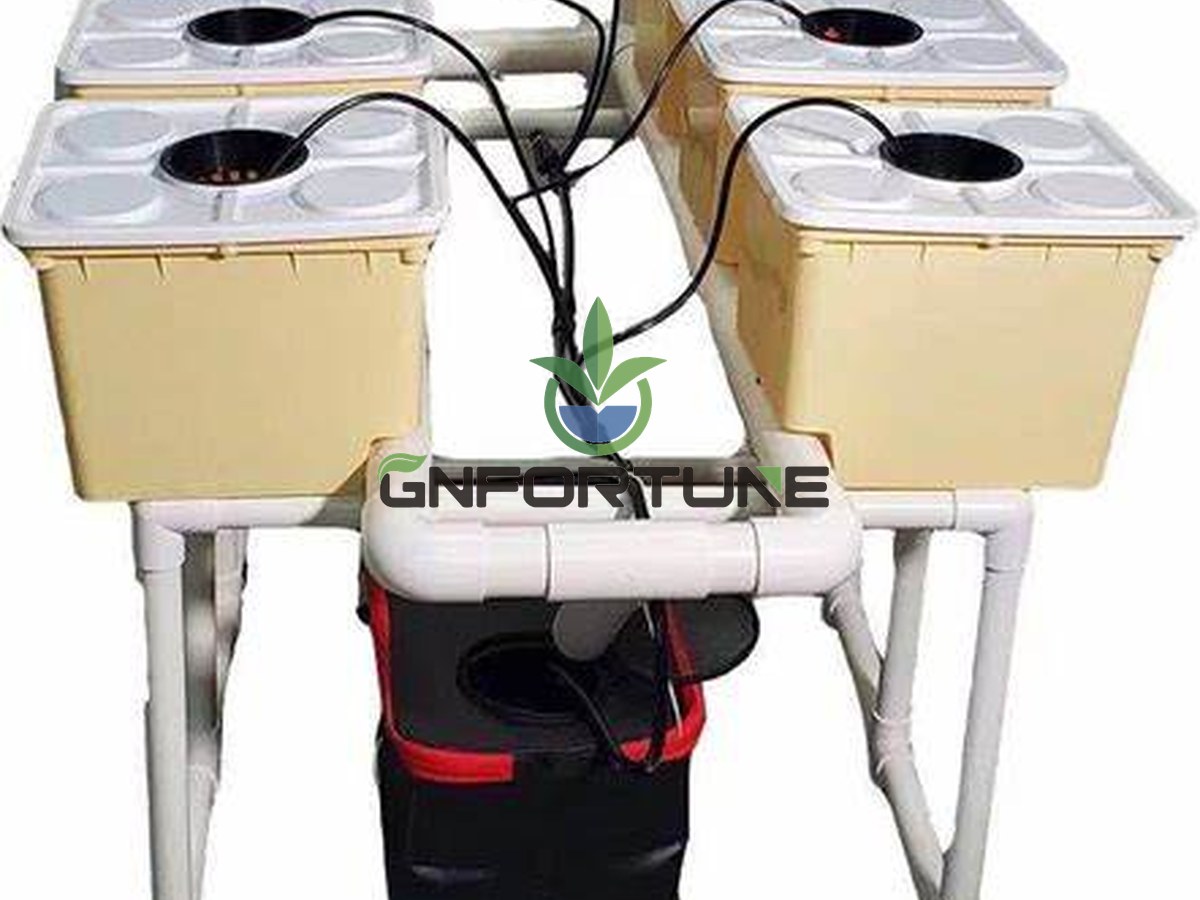
The slope that moves nutrient through a channel in production is not automatically the slope that empties it. A working slope set for film thickness is gentle by design; a drain-down slope has to be steep enough that water actually leaves rather than clinging along the base.
The sections that hold water regardless of the nominal gradient:
- Settlement sags: a run dipping between supports holds a pool, and that is where biofilm starts.
- Couplers and end caps: internal shoulders form small dams, so the outlet should sit at or below the lowest internal surface.
- Hose loops: a hose dipping below the pipe run holds its volume permanently.
- Filter bodies: many housings cannot empty through their own port and need a bowl drain.
Check with water rather than on paper: fill, open the drain, and see what is still standing after the stated drain-down time. Sections that stay full get a revised support or a second drain point.
Flush Point Design: Where Valves Go and What Size
Flush point design follows one rule: put the valve where the debris collects and size it to pass the debris rather than the water. A 25 mm valve on a 50 mm main will pass water slowly and will not pass a root mass, a broken plug or a scale flake.
Placement, in priority order:
- End of every main and sub-main: full-bore where the pipe size allows, because that is where everything travelling arrives.
- End of every manifold: sized to the manifold, not to a convenient tapping.
- Low end of each channel run: channels are cleaned at the ends unless the lid lifts along the length.
- Filter bowls and strainers: before and after, so a housing can be isolated and emptied.
- Tank bottom: a proper bottom drain, not a suction line left to siphon.
Access matters as much as size: a valve behind a rack leg will not be operated weekly, and an unused flush point is blocked when it is needed. Standard pipework and manifold layout practice applies — keep ends accessible.
Flushing Mains: Volume, Time and Where the Water Goes
Flushing mains is a volume problem before it is a time problem. As a planning range, budget 1.5–2.5 times the pipe volume per flush for a clean system, and more where there is a known biofilm or scale history — confirm the multiplier against what comes out of the first flush rather than assuming it.
Time follows from volume and drain size. The plan should state how long the flush runs and who signs it off. “Until it runs clear” is not measurable; a conductivity spot check against the incoming water is.
Discharge destination is the part most often left to the end and then decided badly. Flushed solution has to reach a legitimate destination under local rules, and a full-system flush can exceed what the site drainage was sized for. Confirm the route before positioning the flush point, because the pipe from valve to destination is part of the design.
System Clean-Out Access for Channels, Tanks and Filters
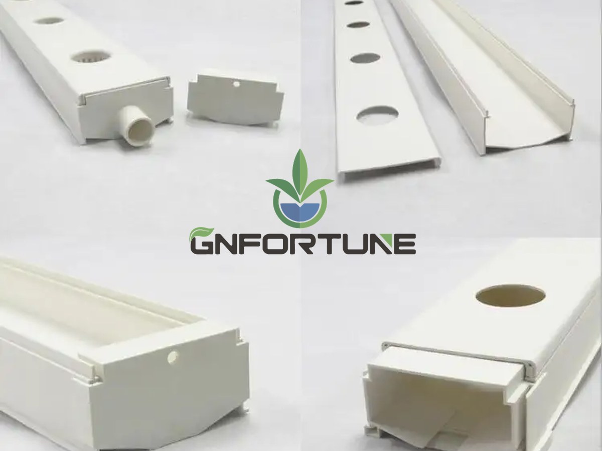
System clean-out access is the physical question behind every valve: can someone reach the part, open it, see inside and put it back. Drainability without access produces a system that empties but is never inspected.
- Channel lids: a lift-off lid makes cleaning a walk-down job; a bonded lid turns it into an end-flush job, fine for short runs and unrealistic for long ones.
- Tank access: a manway or full-open lid plus a light, otherwise it is inspected by feel.
- Filter bowls: clearance beneath to remove the bowl without draining the whole header.
- Suction strainers: removable without breaking the pump coupling.
Channel runs laid out for production often leave no gap for lid removal. The fix is cheap at design stage and expensive afterwards, which is why the channel installation drawing should show the maintenance gap as well as the slope.
Drain Valve Placement in the Greenhouse
Drain valve placement in the greenhouse is where design meets daily hygiene:
- Discharge above the floor into a visible gully or hose connection, not into soil or an untraced pipe.
- Keep the valve out of the crop canopy, where spray and debris collect on it.
- Label every drain point to match the drawing; unlabelled valves get opened in the wrong order.
- Group drains per zone so one zone empties without disturbing zones still in production.
Valves are consumables here. Ball valves sitting wet and unoperated for a season are the usual reason a drain-down “used to work”, and they belong on the spare list.
Commissioning the Drain-Down Before You Need It
Test the drain-down during commissioning, with the system full and before any crop goes in. It is the only time the test is easy:
- Fill to working level and record the volume.
- Open the drains in the specified order and time the emptying.
- Record and photograph what remains standing in each section.
- Flush each main to the stated end point and record the discharged volume.
Those numbers make the cleaning window predictable. A farm that knows its drain-down takes ninety minutes can schedule labour; one that does not discovers the figure on the day the next crop arrives.
FAQs About Hydroponic System Drain-Down
How many drain points does a commercial system need?
One at every low point and dead end: channel low ends, manifold ends, main ends, filter bowls and the tank bottom. A drawing without those points marked is the usual reason a system cannot be fully emptied.
What size should a flush valve be?
Size it to the debris, not to the flow. A valve much smaller than the pipe it drains passes water but not root mass or scale, so the pipe stays dirty even though it empties.
How long should a full drain-down take?
It depends on volume, drain size and discharge capacity, so measure it at commissioning and write the figure into the changeover procedure. Systems that were never timed are the ones that overrun.
Can we flush nutrient solution to the site drain?
Only where local rules and the site’s discharge permit allow it, and only at a volume the drainage was sized for. Confirm the destination before positioning the flush point, not after.
Why does one section never empty?
Usually a low loop, a sag between supports or a coupler shoulder sitting below the outlet. The fix is a revised support or a second drain point at the actual low spot, found by filling and watching.
Related Reading
- Greenhouse Floor Drainage and Hygiene Zoning for Commercial Hydroponic Farms — Where the flushed volume goes once it leaves the system
- Hydroponic Nutrient Discharge: Runoff Rules, Treatment Options and Environmental Compliance — The rules deciding whether your discharge destination is permitted
- Biofilm in Recirculating Hydroponics: Why It Survives Cleaning and How to Manage It — Why sections that never fully drain stay contaminated
- Hydroponic Reservoir Sizing and Water Storage Tank Design for Commercial Farms — Tank volume, bottom drain and the largest drainable section on site
- Hydroponic Spare Parts Inventory: Annual Maintenance Plan for Commercial Farms — Keeping drain valves and seals on the shelf, since they are consumables
Next Step: What to Send for a Quotation
Drainability is quoted from the layout, so the drawing matters more than the component list. A hydroponic system drain down that was never drawn gets improvised at the first changeover, which is the worst possible time to discover it.
Planning a new block or a changeover upgrade? For RFQ or project consultation, send: site layout with dimensions; channel type, run length and quantity; manifold and main sizes; tank set volume and material; discharge destination and any local discharge limits; planned changeover frequency and cleaning method; crop and cycle length; automation level; delivery schedule; and the budget band. G AND N FORTUNE LIMITED supplies NFT channels, tank sets and matched valve and fitting packages quoted to those parameters.