A single-level floor is forgiving. Stack four levels on a rack and the same pump, emitters and pipe sizes stop behaving the way they did on the ground. Multi tier irrigation design is mostly the work of undoing two problems that only appear once crops are stacked: the levels do not see the same pressure, and the water leaving the top level has to pass the lower ones on its way out. Both are solvable on the drawing and both are painful to correct after planting.
This covers the hydraulic organisation only — supply pressure by level, manifold arrangement, run-off collection and service access. Rack structure is covered under rack systems, and the climate differences between levels under vertical farm microclimate.
Why Tiers Do Not Share Pressure Equally
Because gravity does not negotiate. Every metre of vertical separation between two levels is static head the lower level gains and the upper level loses, and the pump only sees one of those conditions.
Four levels at roughly 0.5–0.6 m of separation put about 1.5–1.8 m of height between the top and bottom tier, a static pressure difference in the region of 0.15–0.18 bar. On a non-compensating emitter running at low operating pressure that is enough to move flow per emitter by a visible margin.
- Riser friction: the pipe feeding the upper levels carries the whole rack’s flow for part of its length, so the top of the riser loses pressure dynamically during a watering window too.
- Pump reference point: if the pump and gauge sit at floor level, the reading at the floor is not the reading at the top tier.
The target most designs work to is emitter flow variation within roughly ±10% across a zone. That is hard to hit with ordinary emitters and one zone valve on four levels, and straightforward once each level is regulated.
Multi Tier Irrigation Design Starts With a Pressure Budget
Write the pressure budget before choosing components and the rest follows. A multi tier irrigation design budget lists, in order: pump duty at the worst-case level, riser and manifold friction, the static difference between levels, the pressure required at the emitter, and the margin left for filter fouling.
The order matters because the tightest margin is usually at the top tier during the peak watering window, with several levels open at once. Designing to the average produces a rack that looks fine on day one and goes dry on the top shelf once the canopy closes.
- Fix the emitter type and its designed operating pressure first.
- Add the static head from the pump reference to the highest emitter.
- Add riser and manifold friction at peak simultaneous flow, not at average flow.
- Add the pressure drop across a part-fouled filter rather than a clean one.
- If the remainder is under about 20% of the emitter’s operating pressure, add a regulator per level rather than upsizing the pump.
Tier Manifold Design: One Manifold per Level
Tier manifold design should give every level its own manifold with its own isolation valve, its own regulator where the budget requires one, and its own drain point. A single manifold feeding a vertical dropper to each level is cheaper and is the most common source of uneven watering on stacked systems.
The manifold follows ordinary farm pipework rules with two additions: a gauge port at the far end of each level, because the number that matters is the pressure at the last emitter, and a drain at its lowest point, where the level’s water goes when the zone closes. Standard manifold layout rules still apply: balanced take-offs, one side where possible, accessible ends.
Isolation per level is what makes the system maintainable. Without it, changing one clogged emitter on the second tier means shutting a whole rack, and the crew learns to postpone the work.
Upper Tier Starvation: Symptoms and Causes
Upper tier starvation shows as a persistent size difference between the top level and the middle levels, with top plants smaller and quicker to wilt on a hot afternoon. It is rarely a nutrient problem and almost always a delivery problem.
The causes, in the order they are usually found on site:
- Air in the riser: a partly air-bound riser feeds the top tier last and least.
- Pressure set at floor level: correct at the pump, short at the top emitter.
- Filter fouling: the top tier has the least margin, so it fails first.
- Simultaneous demand: several levels drawing peak flow at once drop riser pressure.
Measure flow at the last emitter on each level with a graduated cylinder over a fixed time, same day and same valve set. The pattern across levels tells you whether the cause is static, dynamic or filtration.
Multi-Level Drainage Hydroponics: Getting Run-off Down
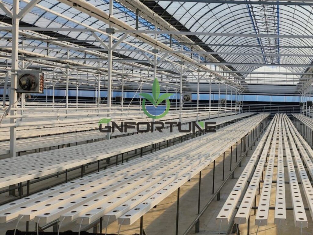
Run-off from an upper level has to leave the rack without wetting the level below. Multi-level drainage hydroponics therefore needs a collection element under every growing level — a shallow gutter, a sloped tray or a channel formed into the shelf — discharging into a common vertical return.
Three failure modes are common. Open-sided trays spill onto the level below, changing its feed and spreading root disease down the rack. Returns discharging into an open floor channel allow aerosol transfer between racks. Returns without a clean-out point make it impossible to flush one level without flooding the ones beneath.
The arrangement that avoids all three is a closed return per level joining a vertical stack, with a flush point at the base of the stack and a sample point where one level’s run-off can be checked alone.

Emitters, Filtration and the Clogging Budget
Vertical rack irrigation concentrates the consequences of clogging. On a floor, one blocked emitter means one dry plant noticed at walking pace; on a rack it means a plant at the back of a shelf nobody sees until harvest.
- Filtration: the rating has to match the emitter’s passage, and the figure that matters is the one quoted by the emitter maker.
- Pressure compensation: compensating emitters remove most of the static head problem above two levels; they do not remove the need for filtration.
- Flushing: every lateral needs a flushable end, or the rack gets cleaned by removing emitters, which nobody schedules.
Budget replacement in minutes per emitter. If reaching an emitter on the third tier means clearing the level above, the honest figure is several minutes each.
Access and Service Routes Between Levels
Access decides whether the hydraulic design survives contact with the crew. The checks that matter are physical and should be done with the rack erected and a full tray in place:
- Can the last emitter on each level be reached without moving plants on another level?
- Can a gauge be read on each level without dismantling anything?
- Is the lighting above protected from water spilled during emitter changes?
Gangways set by rack length rather than by the crew’s reach show up as deferred maintenance rather than as a design defect.
Commissioning Checks Before the First Crop
Commission level by level and record the numbers:
- Fill and vent from the lowest level up, and confirm no air remains at the high points.
- Measure flow at the first and last emitter on every level; record the spread.
- Close each level valve in turn and confirm the others do not back-feed.
- Open each level drain and confirm it empties without discharging onto the level below.
Those readings become the baseline, so a level that drifts later is compared rather than guessed at.
FAQs About Multi-Tier Irrigation
How much pressure difference is there between rack tiers?
Roughly 0.1 bar per metre of vertical separation. Four levels at about 0.5–0.6 m each put the top and bottom tiers roughly 0.15–0.18 bar apart before friction is counted.
Do we need a pressure regulator on every tier?
Where the margin is thin, yes — a regulator per level is cheaper than a larger pump and removes the static difference entirely. On a two-level rack with compensating emitters, one zone regulator is often enough.
Why is the top tier always the one that struggles?
Because it has the least pressure margin, it is where air collects, and it fails first when a filter loads up. Check venting and filtration before changing the nutrient programme.
Should run-off from each level return separately?
Each level needs its own collection element so the tier below is not wetted, but returns can join a common stack. Keep a sample point per level so run-off can be measured where it matters.
How many levels can one pump zone feed?
Less a question of count and more of pressure margin. If peak simultaneous flow drops the top-tier pressure below the emitter’s operating band, split the zone.
Related Reading
- Hydroponic Pump Sizing: Flow Rate, Head Pressure and Redundancy for Commercial Systems — Duty point, head and standby arrangement behind the pressure budget
- Drip Emitter Clogging in Hydroponics: Filtration, Flushing and Emitter Choice — Emitter passage size, filter rating and flushing practice
- Irrigation Filtration: Screen vs Disc vs Sand Filter — Choosing filtration that protects the smallest passage in the system
- Solenoid Valve in Hydroponics: Specifying Zone Valves and Manifolds — Zone valve selection and per-level isolation
- Hydroponic System Commissioning: Installation Sequence, Testing and Site Acceptance — Where the tier-by-tier flow test belongs in handover
Next Step: What to Send for a Quotation
Stacked systems are quoted from the hydraulic design, not from a level count. Multi tier irrigation design priced from “four levels, 40 m long” will be sized from an assumption, usually the average case rather than the peak simultaneous case.
Specifying a multi-tier block? For RFQ or project consultation, send: rack dimensions and number of levels; level separation and clear height; crop and cycle length per level; emitter type and target flow per plant; channel or tray type and quantity per level; water analysis and filtration already installed; zoning and automation level; drainage and discharge requirements; delivery schedule; and the budget band. G AND N FORTUNE LIMITED supplies NFT channels, rack-compatible irrigation components and matched manifold sets quoted to those parameters.