

Drain water is the one flow every hydroponic system produces and almost nobody designs for until the floor is flooded. The drain collection layout — the slopes, gullies and return lines that carry spent solution from every bench, bucket and channel back to a sump or tank — decides whether a blocked outlet is a five-minute fix or a cancelled planting. Plan it backwards from the sump, before channels and buckets are fixed in place, because correcting a fall after construction means lifting floors.
Floor zoning and hygiene rules, and the economics of recycling the water, are covered in their own articles. This one stays on the pipe network itself: gradients, entry points and the fall back to the sump.
What a Drain Collection Layout Has to Answer
A drain collection layout has to answer three questions for every litre that leaves the growing system: where it enters the drain, how it travels, and where it ends. Miss any of the three and the water finds its own answer, usually across the walkway.
The network normally includes four parts, each with its own geometry:
- Entry points: bucket outlets, channel end caps, slab drain stubs and the floor gullies that catch splashes and wash-down water.
- Collection channels: open or grated channels along bench legs or bucket rows, when point drains would be too many to maintain.
- Collection mains: buried or surface pipes that gather the channels and run to a sump, tank or outfall.
- Return lines: the last leg, either a gravity fall to the sump or a pumped lift when the sump sits below the treatment tank.
Draw the whole chain on one drawing. Most of the failures described later start as a gap between two drawings — the channel drawn by one party, the main by another.
Slopes: Floor Falls and Pipe Gradients That Actually Hold
Water needs gradient, but construction reality limits how much you can ask for. A steep fall eats head height at the low end; a shallow fall silts up. The figures below are planning ranges we use when laying out houses; they assume smooth sealed concrete, standard PVC drainage pipe and a competent screed crew, and they should be confirmed against local floor construction practice.
| Element | Planning range | Assumptions and notes |
|---|---|---|
| Floor fall to gully | 0.5–1.0% (5–10 mm per metre) | Sealed concrete; rough screeds need the upper end or standing patches appear |
| Buried collection main, 75–110 mm | 1–2% fall | Gravity mains between houses; sand bed and marker tape assumed |
| Above-ground return line, 50–75 mm | 0.5–1% fall | Short runs back to the tank; supports every 1.5–2 m to hold the gradient |
| Open collection channel | 0.3–0.5% | Long house runs; a shallower fall keeps channel depth reasonable at the outlet end |
| Gully spacing | one per 30–40 m² of wet floor | Assumes 1% floor fall; add gullies at doorways, low corners and under filters |
| Pumped return | no fall needed; velocity ≥ 0.6 m/s | Sized for self-cleansing flow, not for peak; see pump notes below |
Two details decide whether the table survives contact with the site. First, falls must be measured continuously, not just at the ends — a laser level run along the whole line catches the flat spots that a two-point check misses. Second, every support under a surface line must actually hold the fall; a long span between brackets sags into a belly that collects silt and, in winter, the solids that block it.
Gullies and Collection Channels: Where the Water Enters
Entry points fail most often, so place them where water actually goes, not where the drawing looks tidy. That means gullies at the low corner of each house, at doorways where wash-down water gathers, under filter and dosing stations, and at the end of every bucket row where the outlets discharge.
Three placement rules from project work:
- Follow the floor, then set the floor: mark expected flow paths during screeding, and pour to them. Retrofitting a gully into a hardened slab means saw-cutting.
- Grate size over flow, not looks: a grated channel must pass the largest solids the system sheds — root strands from slabs, cocopeat crumbs, spilled media. Fine slots block fast.
- Keep traps serviceable: every gully and channel end needs a removable basket or trap you can lift weekly. A trap nobody can reach becomes a bypass.
Inside the growing area, drain entry points and hygiene zoning belong to one design conversation; the floor drainage and hygiene zoning guide covers the clean-dirty boundaries that decide where entry points may sit.
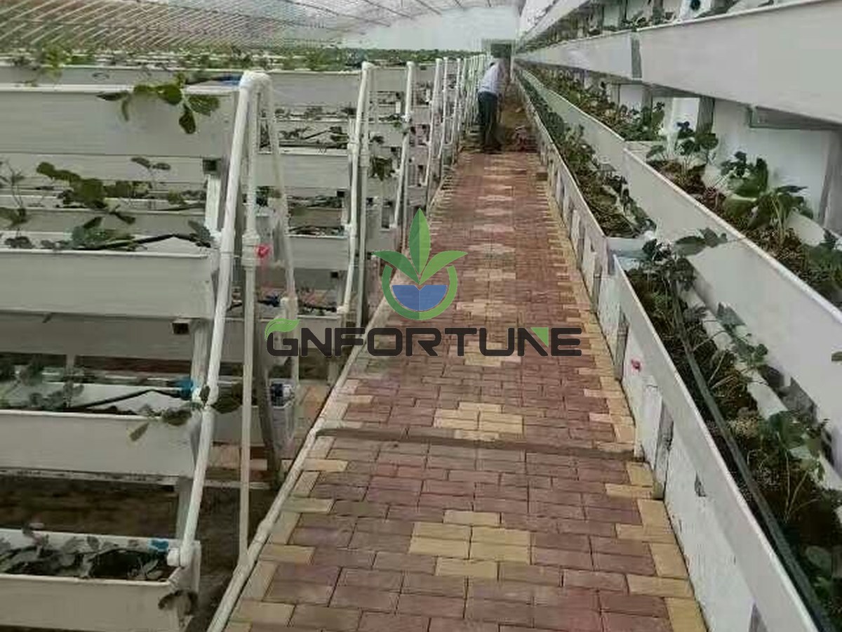
The Fall on Return Lines: Gravity, Lift and Air Pockets
The return line is where layouts get quietly wrong. A gravity return needs continuous fall from the highest entry point to the sump; the highest entry point therefore sets everything downstream. If the last bucket row sits 300 mm above the sump inlet and the run is 40 m, a 0.75% fall uses 300 mm and the geometry just closes — add one high bench more and the line cannot work.
Three rules keep gravity returns honest:
- Start the calculation from the highest entry, not the sump: work forward and confirm the fall budget closes with margin for settlement.
- No high points on a gravity line: a hump forms an air pocket, the flow slows, solids settle, and the line gradually throttles itself. Where a hump is unavoidable, it becomes a pumped section instead.
- Size for self-cleansing velocity: as a planning range, 0.6 m/s or more at typical duty, assuming the flows above, keeps solids moving between weekly flushes.
Where the sump sits below the tank the water must be lifted, and the pump choice then follows the same logic as any dirty-water duty: solids tolerance, cycle frequency and redundancy. The pump sizing guide covers duty point selection; for drain duty, assume the pump passes what the gullies let through, not clean water.
Sump Interface and Zone Separation
The junction where a drain meets the sump deserves its own detail. Discharge above the water line splashes and aerosols; discharge below it siphons back when the pump stops. The usual compromise is an inlet below the working surface with a bend or baffle that breaks direct spray, plus a check element where backflow matters.
Zone separation matters just as much. Independent zones should not share a drain main, because a blocked main in one zone then floods two, and disease containment disappears. Where a shared main is unavoidable — often in retrofits — each branch needs its own cleanout and, ideally, a visible flow check so a crew can see which zone stopped draining.
Whether collected water is then reused at all is an investment question, not a piping one; the comparison of drainage recycling and collection loops handles that decision separately.
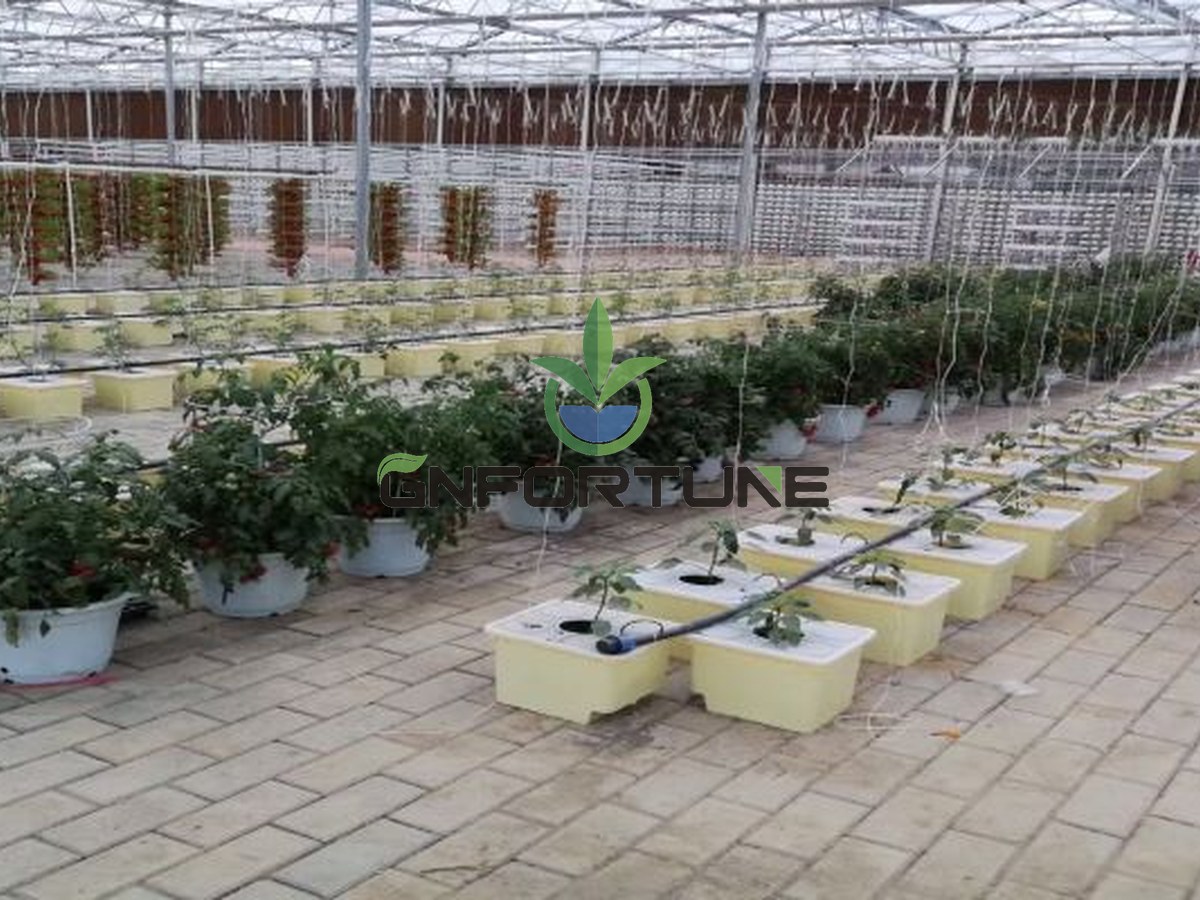
How These Layouts Fail in Practice
Four failure modes account for most of the drain trouble we are called into:
- Flat spots from poor screed control: a 20 mm dip in a 1% floor holds a permanent puddle, algae, then a slippery patch. Laser-controlled screeding costs little extra on new builds.
- Silt and root ingress at joints: buried mains with glued joints in reactive soil move and open. Bedding and flexible joints at risers are the cheap insurance.
- Cross-connections: someone tees a wash-down or chiller condensate line into a nutrient drain, and treatment assumptions quietly change. Every tie-in should be on the as-built drawing.
- Gullies bypassed by “temporary” hoses: a drain hose laid across a walkway lasts one season, then becomes permanent infrastructure nobody owns. Give hoses proper entry points from day one.
A commissioning check catches most of this before crops arrive: run water at each entry point and confirm it appears at the sump within minutes, watch for surging at the pump, and record the result.
A drain collection layout drawn after the fact, from whatever the installer improvised, is a maintenance schedule in disguise. Drawn early — slopes, gully positions and the fall on every return line — it is among the cheapest insurance a wet house can buy.
FAQs About Drain Collection Layout
What fall should a greenhouse floor have toward the drains?
A planning range of 0.5–1.0% covers most sealed concrete floors, assuming gullies are placed at low points and doorways. Rougher screeds need closer to the upper end, and any local dip below the surrounding grade will pond regardless of the average fall.
How far apart should gullies be spaced?
One gully per 30–40 m² of wet floor is a workable starting point at a 1% floor fall, plus extra at doorways, low corners and equipment stations. Spacing is really a flow-path question: if wash water travels more than about 10–12 m to reach a gully, add one closer.
Can return lines run uphill with a small pump instead of a fall?
Yes, and many retrofits do. The pump must handle solids and run often enough to keep the line moving; a pumped return without a check valve also back-siphons on stop. Pumped sections cost electricity and another failure point, so keep gravity wherever the geometry allows.
What diameter should a buried collection main be?
75–110 mm covers most single-house and two-house gravity mains at a 1–2% fall. The better check is velocity: at expected duty the line should carry roughly 0.6 m/s or more so solids do not settle between flushes.
Do drainage rules apply if we discharge to the environment rather than recycling?
Usually yes — nutrient-bearing discharge is regulated in most jurisdictions, and the layout should reserve a sampling and treatment point anyway. The runoff rules and treatment options guide covers the compliance side in detail.
Related Reading
- Drain-Down and Flush Points — The valving that lets a collection network actually be emptied and cleaned
- Hydroponic Pump Sizing: Flow Rate, Head Pressure and Redundancy — Selecting the lift pump at the end of the drain chain
- Hydroponic Reservoir Sizing and Water Storage Tank Design — Where collected water goes and what volume it needs
- Condensate and Chilled Water Recovery — A second, cleaner stream worth routing deliberately
- Hydroponic Water Footprint: Measuring and Reporting Water Use — Why metered drains feed the numbers buyers and auditors ask for
Next Step: What to Send for a Quotation
Drain networks are quoted from geometry, not from catalogues. When collection channels, mains, sump pumps and tie-ins are priced as vague line items, the fall budget between houses gets settled by the installer on the day — usually wrongly.
Planning a build or a retrofit? For an RFQ or project consultation, send: site plan with house positions and levels; number of independent zones and crops per zone; floor construction type and screed tolerance; entry point count (buckets, channels, slabs, wash-down stations); whether collection is gravity or pumped, and the sump location; discharge destination (tank, treatment, or outfall); delivery schedule; and the budget band. G AND N FORTUNE LIMITED sizes collection channels, pipework and sump pumping sets against those inputs.


