On most sites the symptom is visual before it is measured: the last few gutters on a branch look thinner than the first, or the far end never catches up by grading day. Irrigation distribution uniformity is the number behind that pattern — how close the lowest-delivering outlet in one zone sits to the average. When a single manifold feeds a long branch, the gap between the first outlet and the last is rarely the emitters’ fault. It is pressure lost along the pipe, and it reaches the farm as grading loss rather than as a pump room alarm.
This comes from commissioning and troubleshooting: where the pressure goes, what the emitter specification commits to, how to measure the spread, and which fixes last.
What Irrigation Distribution Uniformity Actually Measures
Distribution uniformity compares the lowest-delivering outlets in a zone with the average outlet, expressed as a percentage. It is a property of the hydraulic design, but it sets the ceiling on crop evenness.
As a planning range, commercial leafy houses commonly write 85–95% into commissioning acceptance, assuming clean filtration, correct emitters and a level or documented-graded site. The calculation is simple: sample outlets, sort low to high, average the lowest quarter, divide by the average of all samples, multiply by 100.
It describes the worst-performing part of the zone, which is where complaints start.
Why the Last Outlet Under-Delivers
End-of-line pressure is lower than inlet pressure because water gives up energy as it travels: friction along the pipe wall, every fitting and valve in the path, and any rise in elevation each take a share.
- Friction along the run: loss rises with length and steeply with velocity, so the first metres carrying the whole zone flow cost most.
- Elevation: each metre of rise costs roughly 0.1 bar, starving the high end first.
- Local losses: filters, valves, elbows and take-offs are individually small and collectively significant.
- Uneven loading: a lateral carries full flow at its inlet and almost none at its end.
The deficit concentrates at the end of the longest branch and becomes a flow gradient wherever outlets respond to pressure.
Emitter Flow Variation and Pressure Compensation
Emitter flow variation has two sources: how an emitter responds to pressure, and how much identical emitters differ from one another. Both are published by the manufacturer and easy to miss on a quote that lists only a nominal flow rate.
A non-compensating emitter passes more water at higher pressure; on a short, level run the spread is small. Pressure compensation holds flow across a stated band, which is why PC outlets are specified on long runs and sloping ground.
| Factor | Non-compensating | Pressure-compensating |
|---|---|---|
| Response to pressure | Flow follows pressure | Flow held within a stated band |
| Below minimum pressure | Flow falls away | Acts as a fixed orifice |
| Long or sloping runs | Poor unless regulated | Commonly used, within the rated band |
Compensation has limits: below the stated minimum operating pressure the outlet behaves like a fixed orifice, so PC specification does not remove the need for adequate end-of-line pressure. The diaphragm is a wear item, and undersized filtration raises the clogging risk, which is treated in the drip emitter clogging guide.
Pipe Diameter, Run Length and Elevation Limits
Run length is limited by pressure loss rather than by the greenhouse footprint. The levers are pipe diameter, the number of outlets on one branch, and the pressure at the manifold.
As a planning range on a level, well-filtered house, small-diameter drip laterals are commonly kept within roughly 30–60 m, with sub-mains sized to hold velocity in the order of 1–2 m/s. The real limit depends on emitter flow, spacing and inlet pressure, so check it against the manufacturer’s loss table for the design flow.
Elevation deserves its own line on the drawing: where a site falls across the house, the low end runs wet while the high end runs short, and no emitter change fixes that without regulation or separate zones. On gutter and NFT systems the draining slope also puts the feed at the high end.
How to Measure Drip Line Uniformity on Site
Measure discharge at the outlet, not pressure at the manifold: caught volume is what the plant received, and only that belongs in an acceptance record.
- Run the zone on its normal duty cycle and let pressure stabilise.
- Sample the first, middle and last outlets on the longest and shortest branches, plus a few random points.
- Catch each outlet in a measuring cylinder for a fixed 30–60 seconds and record the volume.
- Convert to litres per hour so readings compare with the emitter specification.
- Sort low to high, average the lowest quarter, divide by the average of all samples, multiply by 100.
- Repeat at the start and end of an irrigation window, recording manifold pressure at the same moment.
A sample of 16–24 outlets is usually enough to rank a zone. Keep filters in their normal state and read at the emitter, or the result flatters the design.
Manifold Balancing, Loops and Flow Restriction
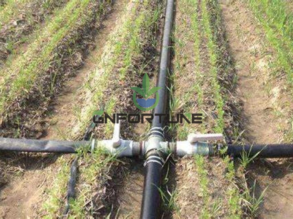
Four measures do most of the corrective work: shorter branches through more zones, larger pipe, pressure regulation at each zone inlet, and restriction on branches that over-deliver. Changing emitters alone rarely fixes a pressure problem.
- More zones, shorter branches: the cheapest fix, because it shortens the distance to the worst outlet; manifold ports must be specified with the zone layout.
- Loop the supply: feeding both ends puts the farthest outlet at most half the run from a feed, at the cost of return pipework and valves.
- Zone pressure regulation: lets branches of different length and elevation share one pump without the short ones robbing the long ones.
- Balancing valves: trim the surplus off over-delivering branches, then re-measure rather than trusting the setting.
- Lower-flow emitters: less branch flow means lower velocity and better end-of-line pressure.
Turning the pump up is not one of them: extra pressure lifts the near end more than the far end and risks pushing outlets past their rated band, which is the pump sizing question. Re-measure after any change, because filters foul and emitters wear.
Where Equipment Selection Comes In
Uniformity is decided on the drawing and delivered through components: channel profile and slope, manifold assemblies, filtration matched to the emitter, and gauges a crew can reach.
G AND N FORTUNE LIMITED supplies NFT channels, gutter and Dutch bucket systems with matched valve, manifold and filtration packages, quoted against the zone layout and emitter specification provided. A gauge at the end of the longest branch costs far less at design stage than after planting.
FAQs About Irrigation Distribution Uniformity
What uniformity figure should we write into a specification?
As a planning range, 85–95% at commissioning is common for commercial leafy houses, assuming clean filtration and a level or documented-graded site. Confirm it with your designer, because it depends on run length, emitter type and manifold pressure.
Do pressure-compensating emitters fix a badly designed branch?
No. They hold flow within a stated band, and below that band the outlet acts as a fixed orifice. Run length, pipe diameter and zone regulation come first.
How many outlets need to be measured?
A sample of 16–24 outlets, including the first, middle and last points on the longest and shortest branches, is usually enough to rank a zone. Bigger samples matter only near the threshold.
Can we raise pump pressure to fix the end of the line?
Rarely. Extra pressure lifts the near end more than the far end. Shortening branches, looping the supply or regulating per zone works better.
Does uniformity change after commissioning?
Yes. Filter fouling, emitter wear, biofilm and seasonal changes in watering duty all move the figure, so repeat the test on a schedule.
Related Reading
- Pipework Runs and Manifold Layout: Farm Rules — Layout rules a balanced manifold respects
- Hydroponic Pump Sizing: Flow Rate, Head Pressure & Redundancy for Commercial Systems — The head the manifold works with
- Solenoid Valve Hydroponics: Specifying Zone Valves and Manifolds — Zone valve specification
- Irrigation Filtration: Screen vs Disc vs Sand Filter — Filtration and clogging risk
- Hydroponic System Commissioning: Installation Sequence, Testing and Site Acceptance — Where the uniformity test belongs
Next Step: What to Send for a Quotation
Irrigation distribution uniformity is quoted from the zone layout and emitter specification, not from a house size: without zone quantities, a supplier assumes a single loop.
Planning a new house or correcting an existing one? For RFQ or project consultation, send: greenhouse dimensions and usable growing area; crop plan and target weekly or annual output; number of zones requested and the length of the longest branch run; emitter type and flow rate, with or without pressure compensation; site levels and any elevation change across the house; local climate range and raw water analysis; automation and monitoring level required; delivery schedule; and the budget band. G AND N FORTUNE LIMITED supplies NFT channels, gutter and Dutch bucket systems with matched valve, manifold and filtration packages quoted to those parameters.