Most layouts put the pressure regulator hydroponic lines need in roughly the right place and the gauges in the wrong one. Uneven pressure reaches the crop before it reaches the equipment log: two blocks fed from the same manifold deliver different amounts, emitters at the far end of a zone run lean, and the pump gets blamed. This article covers which level gets the regulator, whether pressure compensating emitters remove the need for one, where gauges belong, how to pick a dial range, and the setpoint mistakes that survive commissioning.
It is written for engineering teams laying out or re-working irrigation on commercial sites, where the difference between a regulated zone and an unregulated one is visible in uniformity within a single crop cycle.
Pressure Regulator Hydroponic Lines: Which Level Gets It
Regulate at the level where pressure actually varies between the outlets you care about. If every zone on a manifold sees roughly the same inlet pressure and the same elevation, one regulator upstream of the manifold is enough; where zones differ in length, elevation or emitter type, each zone needs its own.
The three levels behave differently:
- Main line regulator: protects downstream components and sets a ceiling for everything after it. It does not correct differences between zones.
- Sub-main or manifold regulator: the usual answer for a group of similar zones fed together, and the cheapest place to start.
- Zone regulator: the answer when zones differ — different elevations, different run lengths, different emitter specifications — because that is where the variation is created.
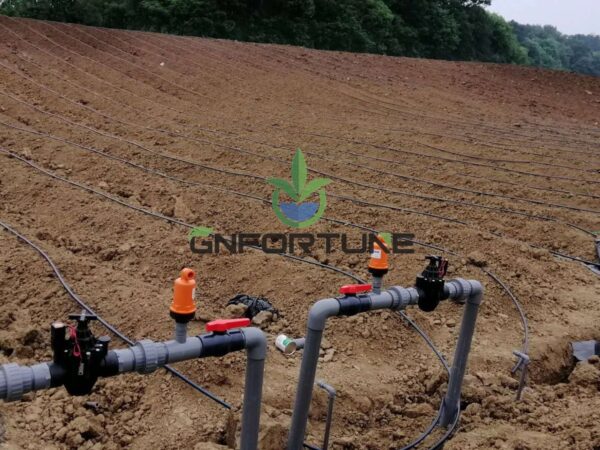
Elevation is the variable most often overlooked. On sloping ground, or in a multi-tier build, the static head difference between the highest and lowest outlets can exceed what any single setpoint can serve, which is precisely when per-zone regulation earns its cost.
Regulator or Pressure Compensating Emitters, or Both
Pressure compensating emitters hold their discharge close to constant across a stated pressure band. A regulator holds the line at a set pressure. They solve overlapping problems and are frequently specified together on the assumption that one is redundant.
| Approach | What it controls | Where it is enough | Limitation |
|---|---|---|---|
| Regulator only | Line pressure at one point | Flat sites, similar zones, non-compensating emitters | Friction losses downstream of the regulator are not corrected |
| PC emitters only | Flow at each outlet within a band | Moderate pressure variation, long laterals | Useless below the band’s lower limit; higher clogging sensitivity |
| Both | Line pressure plus outlet flow | Sloping or tall structures, mixed zone lengths | Higher capital and more items to maintain |
The practical test is the pressure band printed in the emitter specification. If the worst-case pressure at the far end of the zone sits inside that band, compensating emitters alone may be sufficient. If it falls below it, no amount of emitter technology will deliver, and the line pressure has to be raised or the zone shortened.
Emitter choice and its filtration requirement are covered under drip emitter clogging; compensating mechanisms tend to be less forgiving of debris than simple labyrinth paths.

Setpoints, Range and Seasonal Adjustment
Set the pressure at the level the emitters were specified for, not at the level the pump happens to produce. Drip and spray devices are commonly planned in a band around 1–2 bar at the outlet, but the figure that matters is the one in the emitter data sheet, and it should be confirmed with the supplier rather than assumed.
Three points make the difference between a setpoint and a number written on a drawing:
- Measure at the worst point in the zone — the farthest, highest outlet — not at the regulator.
- Record the set pressure and the date at commissioning, so drift can be recognised later.
- Re-check seasonally, because water temperature, filter loading and crop stage all move the duty point.
A regulator also has a minimum flow below which it will not hold its set pressure. Zones that cycle to very low flow, or that close down to a trickle overnight, can fall under that threshold and produce a pressure that wanders rather than holds.
Gauge Placement: Upstream, Downstream and at the Worst Point
Fit a gauge immediately upstream and immediately downstream of every regulator. Upstream confirms there is enough pressure to regulate; downstream confirms the regulator is actually holding. One gauge in the pump room tells you neither.
Beyond the regulator pair, gauges belong where a decision is made from them:
- At the start and end of each zone manifold, so the pressure drop across the zone is visible rather than inferred.
- At the farthest and highest outlet of the zone, since that is the point that fails first.
- Across filters, where the differential reading is what tells you when to backwash or clean.
- On each tier of a multi-level build, because static head makes tier pressure a separate question.
Every gauge needs an isolating valve or a serviceable mount. A gauge that cannot be removed without draining the line will not be replaced when it fails, and a failed gauge is worse than no gauge because it is still read.
Gauge Range Selection
Choose a dial range so the normal working pressure sits near the middle of the scale. A gauge whose working pressure sits at the bottom of a wide dial cannot be read accurately, and one that sits near the top will be destroyed by the first surge.
- Range: working pressure around the mid-scale, with headroom for surge above it.
- Dial size: readable from where the operator stands, not from arm’s length.
- Fill: glycerine-filled dials survive vibration and pulsation better on pump sets.
- Units: one unit system across the site, since mixing bar and psi on the same line invites a setpoint error.
- Snubber or isolation where pulsation from the pump would otherwise oscillate the needle.
Fitting and manifold practice around these components is set out in the pipe fittings and sizing guide and the manifold layout rules; a gauge teed off a turbulent bend reads differently from one on a straight run.
Placement Errors That Survive Commissioning
These are the ones found on sites that otherwise look tidy:
- One gauge in the pump room and none in the field. It reads pump discharge, which is not zone pressure.
- Regulator fitted with no gauge downstream. The setpoint is whatever the installer guessed.
- Regulator upstream of the filter. Filter loading then changes the pressure the zone sees, and the regulator cannot correct it.
- Gauge on the wrong side of a check valve or solenoid, so it reads a trapped pressure rather than the line.
- No gauge at the worst point. The zone is verified at the easiest outlet and fails at the hardest.
- Range chosen to match the pump, not the zone. The needle sits at the bottom of the dial and every reading is a guess.
Commissioning should record a pressure reading at every gauge at full flow, at minimum flow and with one zone isolated. Those three readings are the baseline that later fault-finding uses.
What to Specify in the Order
Regulators and gauges are cheap enough to be treated as consumables and important enough to be specified. Ask for:
- Regulator type, setpoint range, and its minimum flow for stable regulation.
- Where each regulator sits: main, manifold or zone, with the reason recorded.
- Gauge range, dial size, fill and unit system, matched to the working pressure at each location.
- Isolating valve or serviceable mount at every gauge.
- Whether emitter specification makes a regulator redundant, and the pressure band that conclusion rests on.
G AND N FORTUNE LIMITED supplies regulators, gauges and manifold assemblies alongside its irrigation packages, quoted against the zone layout, emitter specification and working pressures you provide.
FAQs About Pressure Regulator Hydroponic Layouts
Where should a pressure regulator go on a hydroponic line?
At the level where pressure varies between the outlets you care about: upstream of a manifold when zones are similar, per zone when they differ in elevation, length or emitter type.
Do pressure compensating emitters remove the need for a regulator?
Sometimes. If the worst-case pressure at the far end of the zone sits within the emitter’s stated compensating band, they may be sufficient; if it falls below that band, line pressure has to be raised or the zone shortened.
Why fit gauges on both sides of a regulator?
The upstream gauge confirms there is enough pressure to regulate, and the downstream gauge confirms the regulator is holding. A single gauge cannot distinguish between the two failures.
What gauge range should we choose?
One where the normal working pressure sits near the middle of the dial, with headroom above for surge. A needle at either end of the scale gives no usable information.
Should the regulator sit before or after the filter?
After it. A regulator upstream of the filter cannot correct the pressure loss that develops as the filter loads, so the zone pressure drifts with cleaning state.
Related Reading
- Drip Emitter Clogging in Hydroponics: Filtration, Flushing and Emitter Choice — Emitter paths, compensating mechanisms and what they tolerate in the water
- Pipework Runs and Manifold Layout: Farm Rules — Layout rules that decide where pressure is lost before the zone starts
- Agricultural Irrigation Pipe Fittings: Types and Sizing — Fitting types and sizing, including how gauges and regulators tee in
- Hydroponic Pump Sizing: Flow Rate, Head Pressure and Redundancy — Where the available pressure at the manifold actually comes from
- Hydroponic System Commissioning: Installation Sequence, Testing and Site Acceptance — Recording the three pressure readings that later fault-finding depends on
Next Step: What to Send for a Quotation
Regulation and measurement are quoted from the zone layout, so the drawing and the emitter specification have to come first. A pressure regulator hydroponic order placed without a setpoint and a gauge range will arrive as a generic part.
Laying out irrigation zones? For RFQ or project consultation, send: greenhouse dimensions and irrigated area; system type and number of zones; zone lengths and elevation differences; emitter type, flow rate and stated pressure band; target flow per zone and per outlet; filter type and position in the line; pump duty point and available pressure at the manifold; automation level requested; local water analysis and climate range; delivery schedule; and the budget band. G AND N FORTUNE LIMITED supplies regulators, gauges and manifold assemblies quoted to those parameters.