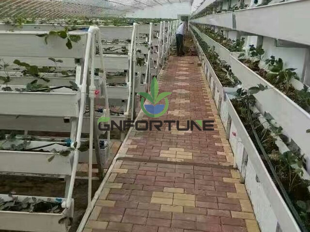
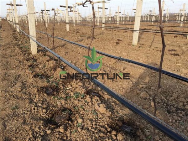
Between two houses, most of a main is out of sight, and that is exactly where the expensive failures happen. A buried pipe run is decided by three details nobody photographs: how much cover sits above it, what it rests on, and how it turns up into the house. Get those right and the line disappears for twenty years. Get them wrong and the connection fails under a path in the middle of a harvest week, with the trench, the slab and the crop all in the way.
How Much Cover Does a Buried Pipe Need?
Cover is measured from the top of the pipe, not the trench floor, and it is set by two conditions: frost where frost occurs, and wheel load where vehicles cross. In a frost-free climate with no traffic above, 400–500 mm is a working minimum for small and medium mains; under a farm vehicle route, 600–900 mm or a concrete slab over the pipe; in frost-susceptible ground, below the local frost depth, often 750–1,000 mm.
| Condition above the line | Planning cover over pipe | Bedding | Watch for |
|---|---|---|---|
| Crop rows or foot traffic, frost-free site | 400–500 mm | 100 mm sand, haunched | Cultivation depth and shallow tines |
| Farm vehicle route | 600–900 mm, or a slab | 100 mm sand plus select fill | Wheel load, not just axle weight |
| Frost-susceptible ground | Below local frost depth, often 750–1,000 mm | Sand, no voids | Frost heave lifting the riser |
| Rocky or rubble fill | 400–500 mm, imported bedding both sides | Sand surround, 100 mm minimum | Point loads on the pipe wall |
| Alongside a greenhouse foundation | 450–600 mm, offset from the footing | Sand, compacted in layers | Foundation load and drainage path |
These are planning ranges for a small-to-medium main carrying nutrient solution at low pressure. Local codes govern where they exist, and a structural check governs wherever a vehicle crosses.
Bedding and Backfill: What the Pipe Rests On
A buried pipe fails from the outside in. Stones in contact with the wall create point loads, PVC cracks and HDPE ovalises; voids under the haunch let the pipe settle and open joints. The fix is cheap and is almost always skipped when a crew is working against a delivery date.
- Trim the trench floor and remove sharp stones, roots and spoil lumps before any bedding goes in.
- Place 100 mm of sand or fine screenings, then bed the pipe and haunch it to the springline so the sides are supported, not just the base.
- Backfill in 200–300 mm layers, compacting each one. Native spoil goes back only above the select fill, and never as lumps against the pipe.
- Lay warning tape 150–300 mm above the pipe, full length, and photograph its position before the next layer covers it.
Compaction matters more than most crews expect. A trench backfilled in one pass settles for a season and takes the riser with it, which is how a line that passed its pressure test in March is leaking at the slab in September.
Risers: Where Buried Pipe Meets the House
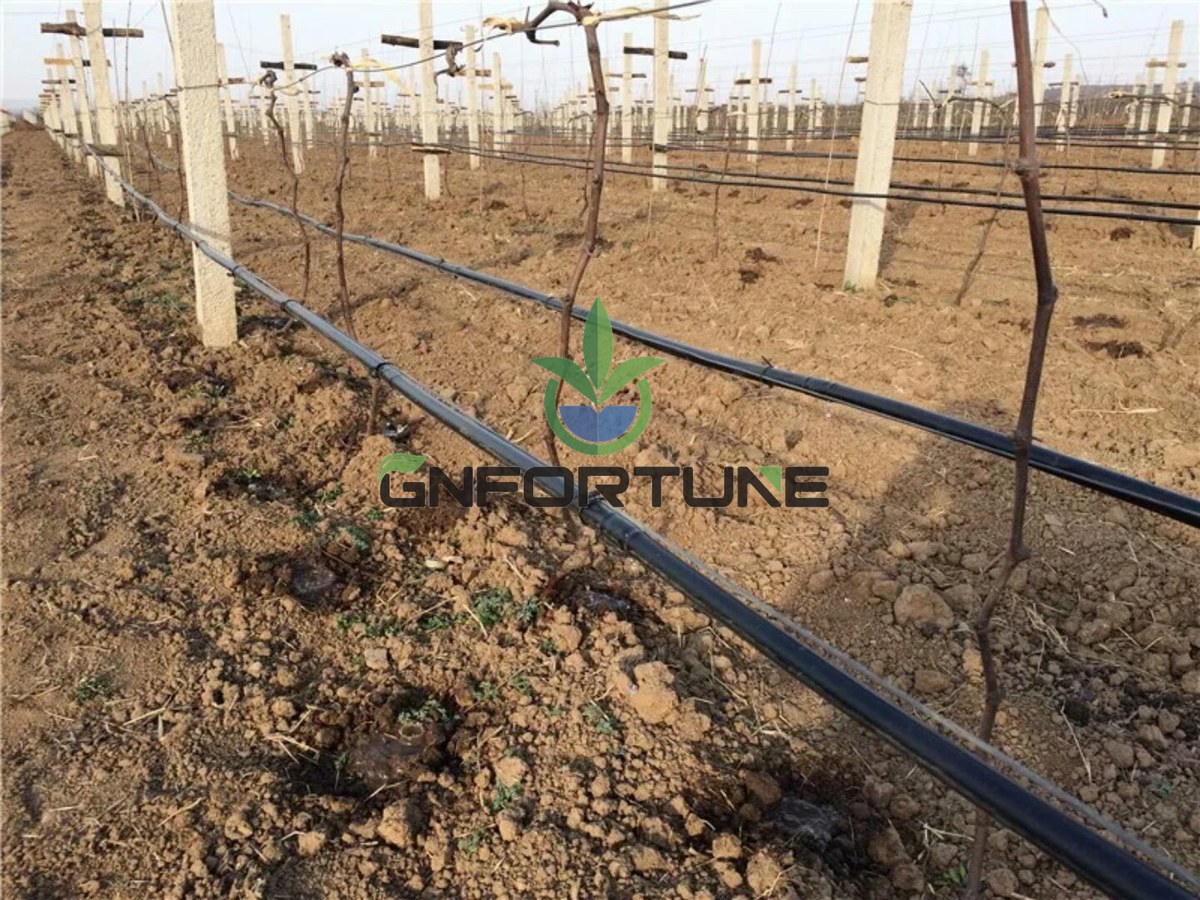
The riser is the most heavily loaded point in the whole run. It carries the transition from a flexible, soil-supported pipe to a rigid, fixed connection, and it absorbs every movement the two sides disagree about. Four details decide whether it survives.
- Use a long-radius transition. Two 45° bends with a short spool between them load the pipe far less than a single 90° elbow at the slab edge.
- Restrain thrust. A buried line under pressure pushes at every change of direction. Thrust blocks, restrained joints or a mechanical anchor at the bend are all valid; none at all is not.
- Support within 300 mm of the bend on the above-ground side, so the riser does not act as a lever on the buried joint.
- Sleeve the slab penetration and seal the annulus, so the pipe is not cast into concrete and can move without cracking at the interface.
Profile, Air and Drain-Down
A buried line follows the ground, and the ground rarely cooperates. Two provisions make the profile workable: a drain point at every low spot, and air release at every high spot. Without them, the line holds water it cannot shed and air it cannot vent.
Where the run can be graded, a fall of about 1 in 200 toward the drain point is comfortable and 1 in 500 is often acceptable; flatter than that and the line will not empty by gravity. Where a high point cannot be avoided, put a chamber and an air valve there rather than hoping the flow pushes the pocket through.
Drain and flush point design is covered in the article on system drain-down and flush points, and the general rules for routing and branch take-offs in pipework runs and manifold layout.
Crossings, Clearances and Damage Prevention
Most buried line damage on farms is caused by the farm itself: a subsoiler, a post knocker or a delivery truck. Three habits reduce it sharply.
- Keep separation from other services. A planning minimum of 300 mm from electrical conduit and 500 mm from any fuel or chemical line, with a 90° crossing where possible, prevents most interference. Confirm against local rules before trenching.
- Mark the route above ground. Marker posts at changes of direction and at both sides of every vehicle crossing cost almost nothing and survive longer than memory.
- Record the line before it disappears. Depth, offset from a fixed structure, pipe material, diameter and the position of every joint. The as-built habit is covered in as-built records and labelling.
Checks Before Backfill
Backfilling is the point of no return, so the inspection list is short and non-negotiable.
- Pressure test the line at the specified test pressure and hold it for the specified period, with joints exposed.
- Confirm bedding depth and haunching along the full length, not just at the ends.
- Confirm the fall is continuous and every low point has a drain.
- Photograph the open trench with a tape measure at each riser and each crossing, then lay the tape and backfill.
None of this is difficult. Buried pipe work fails because it is invisible, rushed and inspected by nobody, and because the crew that digs the trench is rarely the crew that has to repair it.
FAQs About Buried Pipe Runs
What is the minimum cover for a buried irrigation main?
Plan on 400–500 mm where only foot traffic passes in a frost-free climate, 600–900 mm or a slab under vehicles, and below local frost depth where frost occurs. Local codes override these ranges.
Can a buried line be laid directly on excavated soil?
Only if the floor is stone-free and uniformly firm. In practice, 100 mm of sand plus haunching to the springline is the cheap insurance that prevents point loads and settlement.
Why does the riser crack at the slab?
Usually because the pipe was cast into the concrete without a sleeve and then restrained at both ends, so thermal and settlement movement had nowhere to go. A sleeve plus a support within 300 mm of the bend removes most of the load.
Do buried lines need air valves?
At high points, yes. Air collects at the crest and reduces the effective bore, and on a low-pressure line it can stop flow entirely. A small chamber with an air valve is far cheaper than re-excavating later.
How is a buried line leak found without digging it up?
By section isolation and metering: close the zone valves, pressurise one section at a time and watch the meter with all outlets shut. A falling reading locates the section; the marker posts and as-built offsets then locate the spot.
Related Reading
- Greenhouse Pipe Support Hardware — The above-ground half of the same transition
- Water Meters and Leak Detection on Hydroponic Farms — Turning a buried leak into a reading rather than a guess
- Hydroponic System Commissioning: Installation Sequence and Site Acceptance — Where the pre-backfill pressure test belongs in the programme
- Greenhouse Floor Drainage and Hygiene Zoning — Keeping surface water away from the trench line
- Air Lock in Hydroponic Irrigation: Why One Section Stops Delivering — What a buried high point does to flow
Next Step: What to Send for a Quotation
Buried work is priced from a route, not from a pipe length. A quote without a trench profile will be a guess on both sides.
Planning a connection between houses? For RFQ or project consultation, send: a site sketch with distances between houses and sump position; pipe diameter, material and design pressure; ground conditions and water table; what crosses the route above ground; frost depth if applicable; number of risers and slab penetrations; drain and air valve positions; who supplies trenching and bedding; testing requirements; delivery schedule; and the budget band. G AND N FORTUNE LIMITED supplies the pipework, risers, valves and manifolds that fit those routes, quoted to the parameters you send.