
A pump that is running, a manifold that reads pressure, and one section that delivers nothing — that combination is usually air. An air lock hydroponic irrigation fault is a pocket of trapped gas sitting at a high point, at the end of a run or in a filter housing, and it blocks flow to everything downstream of it. It arrives after a fill, a drain-down, a filter change or a pump restart, and on a low-velocity line it often does not clear by itself.
This covers how the air gets in, where it lodges, and the venting routine that keeps it out.
What Air Lock Hydroponic Irrigation Looks Like on Site
The signature is inconsistency: one section delivers nothing while manifold pressure looks normal, flow at an outlet rises and falls without a set-point change, or a row that was fine yesterday is dry while its neighbour is wet.
- A dead section: no delivery at the far end, normal reading at the manifold.
- Variable flow: the same outlet delivers differently between events.
- Intermittent emitters: outlets near a high point work, stop, and work again.
- Spitting at outlets: slugs of air show as spluttering rather than a steady stream.
- Unsteady pressure: the pump runs but the gauge wanders.
The distinction from a blockage matters, because the remedies differ. A blockage is stable and worsens; trapped air changes with filling and time, and can clear after a flush. An air pocket drip line symptom is often treated as clogging for weeks before anyone vents the line.
Where the Air Comes From
Nearly every air lock follows an event: a fill, a drain-down, a filter or pump service, a tank that ran low, or a siphon that emptied part of the line. Air already dissolved in the water is the smaller part of the problem.
- Filling an empty line fast: water runs along the bottom and pushes air ahead into the next high point.
- Drain-down and refill: cleaning, frost precaution or repair leaves the line full of air.
- Pump drawing air: low tank level pulling a vortex, a suction-side leak, a foot valve that does not hold.
- Siphon break: part of the line drains back when the pump stops.
- Filter housings: opened for cleaning, closed with air inside.
- Return above tank level: entrains air continuously rather than once.
Pump-side causes deserve their own check: a suction leak supplies air persistently, which is a pump question rather than a venting one.
High Points, Slope and Velocity
Air moves up and with the flow. Whether a line clears itself depends on whether water is fast enough to carry the bubble to a vent, and whether the pipe rises somewhere the bubble can sit.
- Unvented high points: any rise without a vent collects air; on a long, slow run a few centimetres is enough.
- Undulating runs: a pipe that rises and falls creates several pockets, each holding its own.
- Low velocity: drip laterals and thin films move slowly, so a flush above duty flow is often the only reliable clearance.
- Small bore and emitter inlets: a bubble can lodge at an inlet or connector and behave like a blockage.
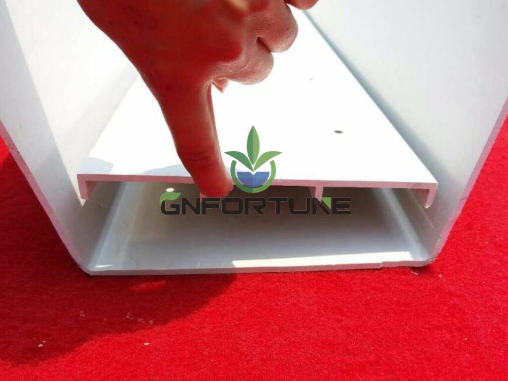
- Channel slope: on a shallow film a pocket breaks the film, and plants above it dry while the channel looks wet.
Continuous fall toward a vent or the outlet end is the design answer. Where the structure forces a rise, that rise needs a vent above it.
Air Release Valves and Vent Points
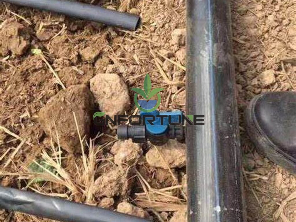
Air needs somewhere to go. An air release valve at each high point, manual vents at the ends of runs and a vent on each filter housing are the difference between a system that clears itself and one that gets stripped down periodically.
- Automatic air release valves: sized and pressure-rated for the line, fitted at high points; they stick and weep, so they belong on the maintenance list.
- Manual vents: cheap, and effective when the crew uses them at the end of each run.
- Vacuum relief: stops siphon drain-back pulling air in when the pump stops.
- Suction side: foot valve, priming arrangement and a tank level that does not allow a vortex.
Specify material compatible with nutrient solution, a pressure range covering working and test pressure, and a serviceable body. Where freezing is possible the vent is a frost risk itself.
Priming and Venting Procedure
Fill slowly, vent deliberately, and prove delivery at the outlet before calling a zone live. Most air locks are created by the fill itself.
- Isolate the section and open the vent at its high point and at the far end.
- Fill from the supply end at reduced flow, so water advances as a front and pushes air ahead rather than over it.
- Close each vent only when water comes out without spitting.
- Bring the pump to duty speed and hold it; a short period at full flow clears more than a long trickle.
- Check delivery at the far end and last outlets before the zone is declared live.
- Re-check after the first full cycle, and after any filter or pump service.
Never commission a zone on pressure alone: manifold pressure says nothing about the last outlet, and filling several zones at once lets air take the path of least resistance.
Trapped Air in NFT Channels and Drip Laterals
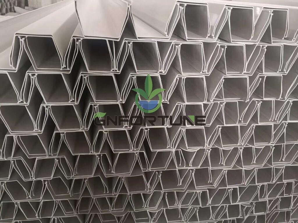
The two trap air in different places: channels at the inlet and under lids or mats, laterals at high points and emitter inlets.
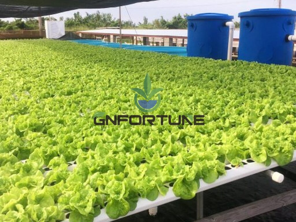
On a channel system the symptom misleads — the channel looks wet, but a pocket under a lid lifts the mat off the film and the plants on that section dry. Slope and inlet detail decide whether the run clears itself, which is covered in the channel slope and flow rate guide.
On laterals the practical measures are opening the ends, flushing above duty flow, and checking the end fittings where air tends to sit. After a drain-down, expect the first cycle to be uneven and plan to re-check it.
Where Equipment Selection Comes In
Venting is a design item that costs almost nothing early and becomes disruptive later, because retrofitting a vent means draining a planted zone. Channel profile, end caps, connectors, valve positions and the priming arrangement are specified together.
G AND N FORTUNE LIMITED supplies NFT channels, gutter and Dutch bucket systems with matched end caps, connectors, valves and vent fittings, quoted against the layout and the venting points specified.
FAQs About Air Locks in Hydroponic Irrigation
How do we tell trapped air from a blockage?
Air changes: delivery varies between events, outlets spit, and a flush sometimes fixes it. A blockage is stable and worsens, so a fault that clears after venting was air.
Will an air lock clear on its own?
Small pockets pass with flow, but a pocket at an unvented high point can persist. Expect it to stay until the line is vented or flushed at higher velocity.
Where should air release valves be fitted?
Above every high point, at the ends of long runs, on filter housings, and on the pump side where priming requires it. A vent with no service access will be ignored.
Do NFT channels need air release valves?
Channels usually vent through their ends and lids; the supply pipework is where vents matter most. Check that the mat stays in contact with the film along the run.
Can trapped air damage the pump?
Yes. A pump working against a locked line, or drawing air through a suction leak, runs outside its intended condition and should be stopped and investigated.
Related Reading
- Pipework Runs and Manifold Layout: Farm Rules — Layout rules that decide where high points end up
- How to Install NFT Channels: Layout, Slope & Flow Rate Guide — Slope and flow rate that let a run clear itself
- Hydroponic Pump Sizing: Flow Rate, Head Pressure & Redundancy for Commercial Systems — Suction conditions and duty flow
- Hydroponic System Commissioning: Installation Sequence, Testing and Site Acceptance — Where the priming and venting record belongs
- NFT Channel Accessories: End Caps, Connectors and the Spares Kit to Order Up Front — End fittings and vents to order with the channels
Next Step: What to Send for a Quotation
Air lock hydroponic irrigation faults are prevented on the drawing: venting and priming are quoted from the layout, not from a house size. Without pipework levels and run lengths, vents get placed where they are convenient to build.
Planning a new house or chasing a recurring air lock? For RFQ or project consultation, send: greenhouse dimensions and usable growing area; system type and channel profile with run lengths; pipework levels and any forced high points; zone count and manifold arrangement; pump type, priming arrangement and tank arrangement; filtration stages and housing locations; crop plan and target weekly output; local climate range including frost risk; automation level required; delivery schedule; and the budget band. G AND N FORTUNE LIMITED supplies NFT channels, gutter and Dutch bucket systems with matched end caps, connectors, valves and vent fittings quoted to those parameters.