Pipework Runs and Manifold Layout: Farm Rules
Pipework is the part of a hydroponic layout that is hardest to change later, and the part most often drawn last. Irrigation manifold design decides what a farm can flush, isolate and extend for the next decade, and it is cheaper to get right on paper than to cut open a slab for. The rules below cover starting from drainage, sizing mains on velocity, spacing manifolds per bay, giving every low point a drain and every bay a valve, and leaving capped spare ways for the next phase.
Start From the Drainage, Not the Supply
Draw the system backwards. Mark where water leaves every run — tank return, floor drain, flush outlet, sump — then route the supply to serve that drainage path. Supply drawn first produces flat runs with nowhere to go, and a flat main cannot be drained or flushed.
- Fix the tank and sump position first: everything else slopes toward them.
- Decide return type per zone: recirculating returns go back to the tank, drain-to-waste zones need a legal discharge point.
- Size the return for the flush case: the drain line has to carry a full flush, not a trickle.
- Keep returns separate by crop zone: herbs and lettuce on one return means one feed change reaches both.
Returns should run by gravity where the layout allows. At 0.5 to 1% slope, roughly 5 to 10 mm per metre, a gravity return avoids a second pump and gives a visible check that flow is running.
Main Sizing and Loop vs Dead-End Runs
Mains are sized on velocity, not on the pipe size left over. Holding velocity between about 1.0 and 2.0 m per second limits pressure loss, water hammer and the scouring that carries grit into emitters; most layouts sit near 1.5 m per second.
| Nominal size | Flow at about 1.5 m per s | Typical duty on a farm |
|---|---|---|
| 32 mm | about 4 m³ per h | Single bay feed |
| 40 mm | about 7 m³ per h | House sub-main |
| 50 mm | about 11 m³ per h | Bay manifold |
| 63 mm | about 17 m³ per h | House main, several bays |
| 75 mm | about 24 m³ per h | Main, several houses |
| 90 mm | about 34 m³ per h | Large house main |
| 110 mm | about 51 m³ per h | Site main or loop |
A looped main returns to the pump station by a second path, so any section can be isolated without starving everything downstream and pressure evens out along the length. A dead-end main is cheaper and shorter, but pressure drops toward the far end, sediment collects where there is no through-flow, and one repair shuts the whole run.
Loop the main past roughly 30 to 40 m, where more than four bays hang off it, or where crop value justifies not shutting a house down for a fitting. Material choice follows: PVC is stiff and solvent-welded, PE flexible and tolerant of ground movement. The PVC versus PE comparison for irrigation mains sets out where each pays.
Manifold Spacing Per Bay
A manifold is the header feeding a group of channels or drippers from one controlled point. Space them so one valve isolates one workable unit, not half a house and not two channels.
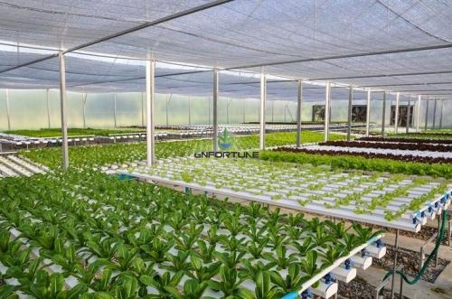
- One manifold per bay: the default on gutter houses, so a bay can be flushed, drained or replanted alone.
- Four to eight channels per manifold way in NFT, matched to the flow each channel needs.
- Feed long headers from both ends past about 20 to 30 m, or from the centre, so far take-offs are not starved.
- Fit a balancing valve on each way so distribution can be set at commissioning and re-set later.
Keep the header at the same velocity discipline: 50 mm feeding eight NFT channels is typical, 32 mm suits a single rack. Take-offs should leave the top or side, never the bottom, so grit reaches the flush point.
Slope, Low Points and Drain Valves
Every run that holds water needs a way out: slope mains at 0.5 to 1% toward a drain point, a drain valve at every low point, an air release at every high point.
Drain valves should be full bore, 25 to 40 mm by line size, discharging to a visible gully or sump rather than onto the floor. On site we often see drain points discharging into a closed trench, so nobody confirms the line emptied.
| Point | Fitting | Size guide | Purpose |
|---|---|---|---|
| Low point on a main | Full-bore drain valve | 25 to 40 mm | Empty the run |
| End of a manifold | Flush valve or capped tee | Match header | Flush sediment |
| High point | Air release valve | 15 to 25 mm | Stop air locks |
| Bay take-off | Isolation valve | Match take-off | Shut one bay |
| Pump discharge | Isolation plus gauge | Match main | Set duty, read blockages |
| Return before tank | Sampling point or meter spool | Match return | Read EC, pH and flow |
Channel slope is a separate and steeper number: NFT channels are commonly set at 1 to 2%, and the interaction between slope, length and flow is covered in the NFT channel installation guide on slope and flow rate.
Isolation So One Repair Stops One Bay
Isolation is the difference between a short repair and a lost crop: any component that can fail should be removable without stopping anything else.
- Valve per bay on feed and return, so a bay can be isolated and drained while the house runs.
- Valve per manifold so a header can be pulled without touching the main.
- Valve per pump on suction and discharge, duty and standby each fully valved.
- Valve per tank so a tank can be drained without shutting the farm.
- Unions at every pump, filter and meter so items come out without cutting pipe.
A valve schedule drawn on the plan is worth more than any pipe size, because it is what the crew reads first. The failure mode we keep meeting is one isolation valve for the whole house: a leaking fitting at the far end means draining the main, and the tail of the run sits dry for half a day.
Label every valve with a number matching the drawing, and keep labels legible after a season of UV and sanitiser. Fit flow and pressure readings where they can be seen without a ladder, since those two numbers find a blocked filter before the crop shows it.
Future-Proofing: Capped Tees and Spare Ways
Farms extend in phases, and pipework is the expensive part to revisit. Three provisions at install time avoid most of the rework.
- Capped tees at main ends: the next bay connects to a tee already under pressure test, not to a cut in a live line.
- One or two spare ways per manifold: blanked off at install, available when a row is added.
- Spare capacity in the main: size for phase two, since the pipe costs little more and the trench costs the same.
Leave meter spools where sensors will be added later. Meter placement and the night-flow leak method are covered in the water meter and leak detection guide, probe siting in the sensor placement guide. Both are easier to serve if a tee and valve exist.
Filtration belongs in the same drawing. Emitter protection is covered in the drip emitter clogging guide, and fittings in the pipe fittings guide.
Frequently Asked Questions
What slope should a hydroponic main run at?
A: 0.5 to 1%, about 5 to 10 mm per metre, sloping to a drain valve at the low point. NFT channels run steeper, usually 1 to 2%.
How do I size an irrigation main?
A: On velocity held between about 1.0 and 2.0 m per second, designed near 1.5. Oversize for the second phase.
Should the main be looped or dead-end?
A: Loop it past roughly 30 to 40 m or four bays. A dead-end run loses pressure at the far end and one repair shuts the line.
Where do drain valves go?
A: At every low point, full bore at 25 to 40 mm, discharging to a visible gully or sump. Add air release at high points.
How many channels should one manifold feed?
A: Four to eight NFT channels per way is typical, with one manifold per bay so a bay can be isolated alone.
Request a Pipework Drawing With Your Quote
Pipework runs and manifold layout come down to five decisions: where water leaves the system, the velocity the mains are sized to, manifolds per bay, drain and isolation points, and what the next phase needs. Pipework layout greenhouse decisions made late cost more than any other line in the bill, because they are buried and covered by the time anyone notices.
Send the house dimensions, bay layout, channel count and flow per channel, tank position and any phase plan, and the engineering team will return a main and manifold sizing, valve schedule and drain point list. To request a pipework drawing with your quote, state whether the site drains to a tank return or to waste, since that sets the slope direction.