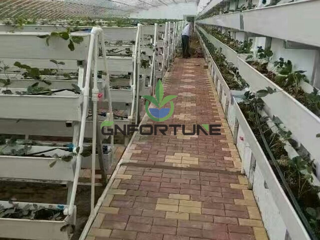
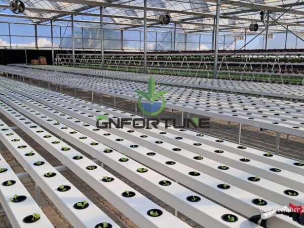
Every NFT layout review reaches the same question: how long can one channel be before the last plant stops performing like the first? The honest answer is that nft channel run length is not limited by the extrusion. It is limited by four things that happen along the way — flow gets consumed, slope error accumulates, solution warms up, and EC climbs. Any one of the four can set the ceiling.
The four are set out below with planning ranges and the measurements that confirm them on site.
What Sets an NFT Channel Run Length Limit
An NFT channel run length limit is set by the worst of four constraints, not by how long the extrusion can be produced. Channels ship in standard lengths and joining them on site is routine; the ceiling appears when what reaches the first plant is no longer what reaches the last one.
The four constraints:
- Flow consumed along the run: every plant takes solution, so the film thins toward the outlet.
- Slope error and deflection: over a long run, small gradient errors and support sag produce low spots and standing solution.
- Temperature rise along the run: solution warms as it travels through a lit house, and dissolved oxygen falls as it warms.
- EC rise along the channel: water is taken up faster than nutrients, so the film concentrates before it reaches the outlet.
Which one governs depends on the site. A cool, well-ventilated house with generous flow usually meets the flow or slope constraint first; a hot house with modest flow meets temperature and EC first.
Constraint One: Supply Flow Versus What the Crop Consumes
Start with the delivery rate. A planning range of 1–3 L/min per channel is commonly used for a 100×50 mm NFT channel carrying leafy crops at a 1% slope, with the higher end applied to dense canopies in warm conditions. Larger sections sit at the top of that band or above it.
The check is not whether inlet flow matches the design figure. It is what arrives at the outlet:
- Measure inlet flow at the manifold and outlet flow at the far end, under full canopy and at peak demand.
- Compare the two. A large drop means consumption and channel friction are competing with the specified flow.
- Watch the film over the last 2 m. A film that thins to a trickle at midday is the visible symptom of the same problem.
Pump capacity is the upstream half of this. The duty point has to cover every channel on the zone at peak demand, which is set out in the pump sizing guide.
Constraint Two: Slope, Sag and Where Solution Stops Moving
A nominal 1% slope is easy to specify and harder to hold over 20 m. Error accumulates with length:
- Support tolerance: each bracket sets a height, and a small error per support becomes meaningful across many supports.
- Deflection under load: a full channel plus canopy sags between supports, so the low point sits mid-span rather than at the outlet.
- Structural movement: greenhouse frames and suspended supports move with thermal and wind load.
Standing solution at a low point is the failure mode that matters: roots sit in stagnant film, oxygen drops, and plants at that position show it first. Where long runs are unavoidable, survey the installed slope with a level or laser at commissioning rather than trusting the bracket setting.
Installation method, bracket spacing and slope verification are covered in the NFT channel installation guide.
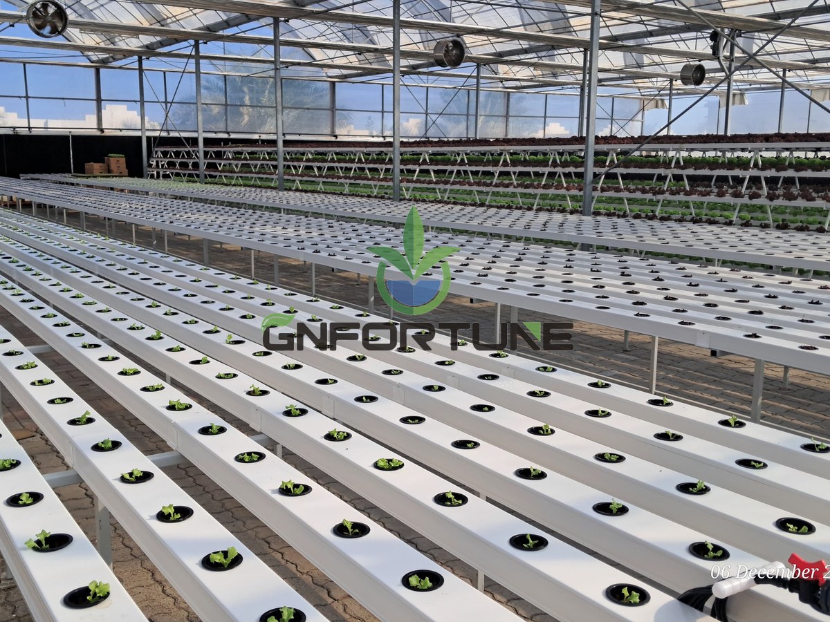
Constraint Three: Temperature Rise Along the Run
Solution entering at tank temperature warms as it travels through a lit greenhouse, particularly where the channel is exposed and flow is slow. Warmer solution holds less dissolved oxygen, and that is the variable roots respond to first.
A planning range of 1–3 °C rise between inlet and outlet is a reasonable expectation for a covered, ventilated house at moderate flow; exposed channels in a hot climate at low flow can exceed it. Two levers move it:
- Flow rate: faster throughput means less residence time and less heat gain per litre.
- Shading and elevation: keeping the channel out of direct sun and away from the hottest air layer near the roof cuts the gain.
Where outlet temperature is the binding constraint, sectioning the run achieves more than any other change, because it halves residence time.
Constraint Four: EC Rise Along the Channel and Disease Reach
Water is taken up faster than nutrients, so the film concentrates as it travels. EC rise along the channel is a length effect rather than a recipe error: the same feed produces a different reading at the outlet than at the inlet.
A planning range of 0.2–0.5 mS/cm between inlet and outlet is typical for a healthy leafy run under peak transpiration; a wider gap usually indicates flow is too low or the run too long. Sample at the same clock time and the same days after transplant, because the value moves with canopy and weather.
Length also sets how far a problem travels. A root pathogen entering at one plant is carried downstream through the whole run, so a short run exposes fewer plants per event than a long one. That is an argument for sectioning that has nothing to do with uniformity.
A Planning Range for NFT Channel Run Length
The bands below assume a single feed point at the upstream end and a free-draining outlet, on leafy crops with a full canopy. They are a starting layout, not a specification — confirm with the inlet-to-outlet measurements described above.
| Condition | Planning range, one feed run | What usually governs |
|---|---|---|
| 100×50 mm channel, 1–2 L/min, temperate house | 10–15 m | Flow and slope |
| 73×62 mm MGS channel, 2–3 L/min | 12–20 m | Flow; larger section carries more |
| Hot climate, exposed channel, peak summer | 8–12 m | Temperature and EC rise |
| Cool climate, shaded channel, high flow | 15–20 m | Slope and deflection |
| Heavy canopy or long-cycle crop | 8–12 m | Consumption along the run |
Channel section changes the flow side of this directly, so the channel size comparison and the run length decision belong in the same conversation. A site that measures well can run longer than the band; one that measures badly should not argue with its numbers.
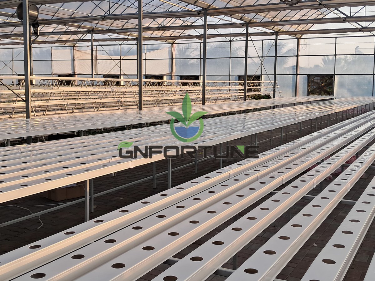
Measuring the First-to-Last Plant Difference
The number that settles the argument is the difference between the first and last plants. A workable protocol:
- Pick three runs that represent the zone, not the best one.
- Sample at the inlet and the outlet of the same run at the same clock time, on a hot day with full canopy. Record temperature, EC and pH.
- Score or weigh plants at the first, middle and last positions across several cycles.
- If the last position under-performs consistently, shorten the run or raise flow rather than adjusting the recipe.
Do this before the layout is frozen. Retrofitting a mid-run feed point after the channels are populated costs far more than setting the length correctly at design stage.
Sectioning Long Runs: Feed Points and Zones
When a bay is longer than the run limit, three options exist:
- Split into independent runs with separate feed and return: cleanest hydraulically. Costs more manifold, more valves and more drain points.
- Feed from both ends toward a centre collection: halves effective travel distance without doubling the manifold, but the two halves must be balanced deliberately.
- Intermediate feed point on a continuous channel: the least invasive retrofit. It helps flow and temperature, though the downstream section still carries what the upstream section sheds.
Whichever is chosen, the zone boundary should follow the hydraulic split. A zone that spans two independently fed runs produces two sizes of plant and no way to correct them separately.
The nft channel run length that survives commissioning is the one fixed by these four constraints, not by the bay drawing.
FAQs About NFT Channel Run Length
What is the maximum channel length for a hydroponic NFT system?
There is no single figure. Plan on 10–20 m for a single feed run on leafy crops, with 8–12 m in hot climates or under heavy canopy. The limit is the point where inlet-to-outlet differences in flow, temperature or EC start showing in plant size.
Does a steeper slope let us run longer?
It helps with ponding but not with the other three constraints. Steeper slope raises velocity and thins the film, which can reduce root contact time on long runs. Slope should be set for drainage, not used to buy length.
How does channel length affect the flow rate we need?
Longer runs need more inlet flow to deliver the same film at the outlet, because the crop consumes solution along the way and friction grows with length. Size the pump against outlet flow, not inlet flow.
Why is EC higher at the end of the channel?
Plants take up water faster than nutrients, so the remaining solution concentrates as it travels. A gap of roughly 0.2–0.5 mS/cm between inlet and outlet is normal under peak transpiration; a wider gap points to low flow or an over-long run.
Can a bigger pump fix a long run?
Sometimes. If flow is the binding constraint, more throughput helps. Where slope, temperature or EC rise is binding, extra flow only masks the symptom and raises energy cost — sectioning the run is the durable fix.
Related Reading
- How to Install NFT Channels: Layout, Slope and Flow Rate Guide — Bracket spacing, slope verification and the flow checks that follow
- NFT Channel Sizes: 100×50mm vs 73×62mm Compared — How section size changes the flow a run can carry
- Hydroponic Pump Sizing: Flow Rate, Head Pressure and Redundancy — Sizing the duty point against outlet flow at peak demand
- Commercial Lettuce Production in NFT Channels — The crop most run-length decisions are made for
Next Step: What to Send for a Quotation
Run length is a layout decision that turns into a bill of materials. Once the limit is set, manifold count, valve count, drain points and pump duty all follow; a layout quoted before that decision is usually revised after it.
Planning an NFT block? For RFQ or project consultation, send: bay dimensions and target growing area; channel section preference (100×50 mm, 73×62 mm MGS or openable lid); available slope and floor flatness; crop and expected canopy; number of zones required; peak ambient temperature and relative humidity range; raw water analysis; pump and automation level; delivery schedule; and the budget band. G AND N FORTUNE LIMITED supplies NFT channels, manifolds, pumping sets and matched greenhouse packages quoted to those parameters, with in-house extrusion and injection capacity for custom sections.