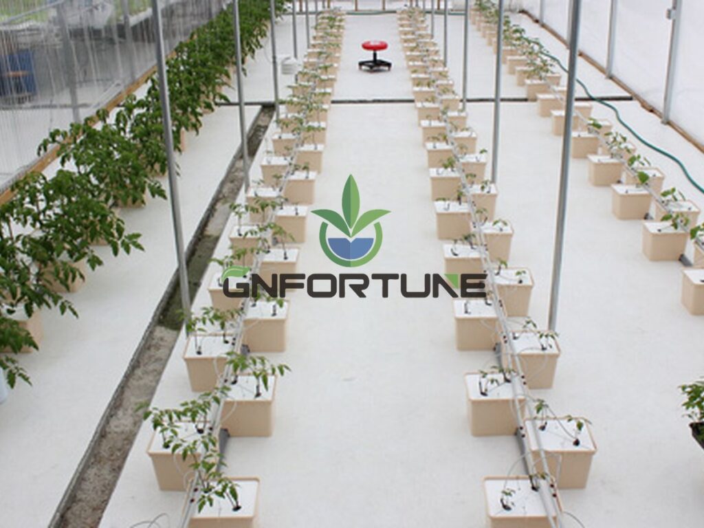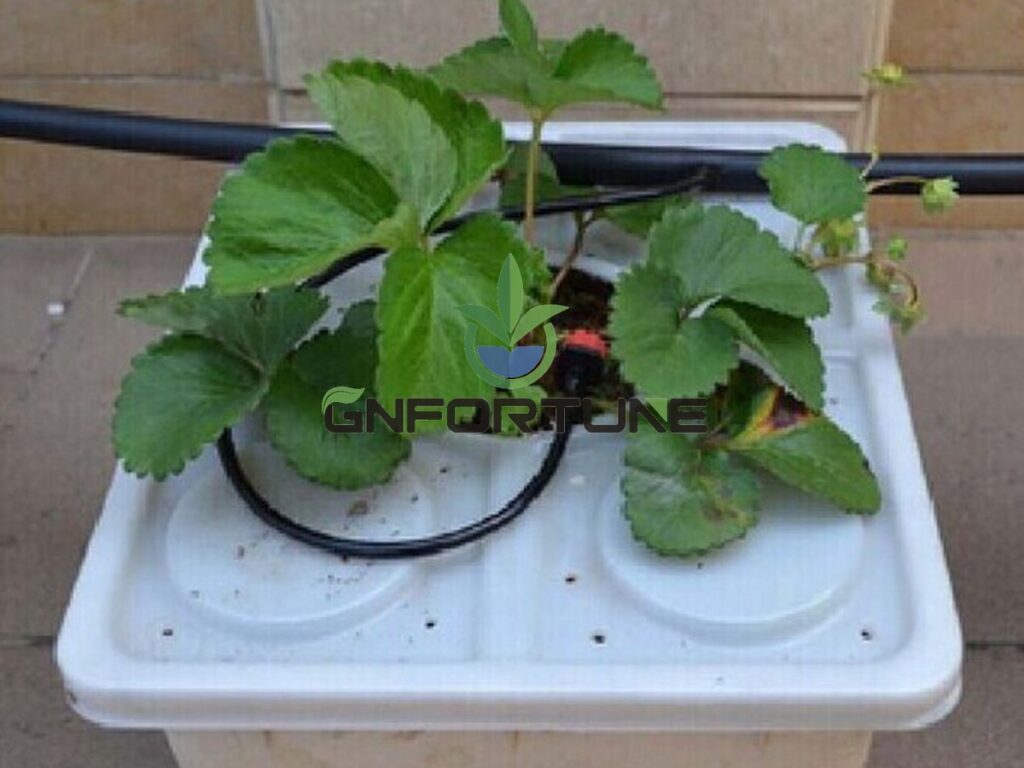
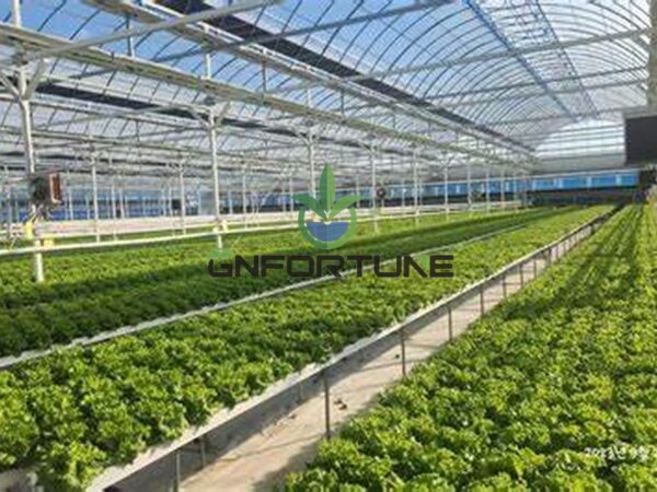
A CO2 system can dose perfectly and still waste most of its gas. What the plants experience is not the dosing rate on the controller but CO2 distribution — whether the enriched air actually reaches the leaf surface, everywhere in the house, while the vents are doing something predictable. Duct placement, shoot direction and sensor height decide that. Get them wrong and one end of the house grows on enrichment while the other grows on ambient air, with one controller reporting a number that describes neither.
Equipment selection and dosage sizing are covered separately in the guide to CO2 enrichment equipment and the dosage arithmetic behind how much CO2 plants need; this article is about moving the gas once it exists.
Where the Gas Enters: Ducts, Burners and Release Points
Distribution starts with the source’s own pattern. Liquid CO2 dosing through a distributor, combustion from a burner, and ducted supply from a sealed room all put gas into the air differently, and each carries its own placement rules:
- Burner units: the exhaust plume is hot and buoyant, so it climbs. Place burners where the rising plume spreads across the ridge air rather than punching straight out through an open vent, and where combustion products are not dumped directly onto one canopy section.
- Liquid CO2 release points: the gas leaves cold and initially sinks slightly before mixing. Overhead release with gentle downward spread generally beats floor-level release, which pools in cold pockets under benches and gutters.
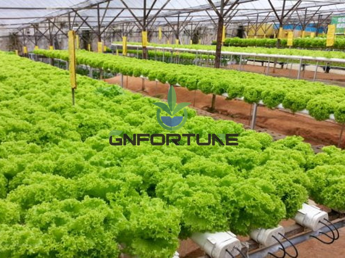
- Perforated ducts: the most controllable option. Lay ducts along the rows above the canopy with holes oriented to shower air downward into the crop, so enrichment is delivered where uptake happens rather than at the ridge.
The choice among these hardware options is covered in the CO2 enrichment equipment comparison. The distribution rule behind all three is the same: introduce gas into air that is already moving toward the canopy, and never into still air that will stratify.
Shoot Direction: Into the Canopy, Along the Rows
The direction a release shoots matters as much as its height. Two principles from project practice:
- Downward and along the row beats across the aisle. Gas aimed down the length of a crop row follows the channel of air between canopies and reaches leaf surfaces along the whole run; gas fired across an aisle mostly hits the first canopy face and skips the far end.
- Follow the airflow, never fight it. Under HAF circulation and vent-driven flow, air travels in defined loops. Release points should inject into those loops — upstream of the crop, downstream of the vents — rather than opposing them, which short-circuits fresh gas straight to the ridge and out.
When vents are open, the floor of the house becomes a crosswind: gas released low on the windward side never crosses the room. The robust layouts put distribution above the canopy where the air path is steadier, or use ducts whose holes span the row so delivery survives wind changes. The airflow patterns themselves — vent design and HAF fan layout — are set out in the ventilation design guide, and CO2 placement should be reviewed against that drawing, not against guesswork.
Sensor Height: Measuring What the Plant Actually Sees
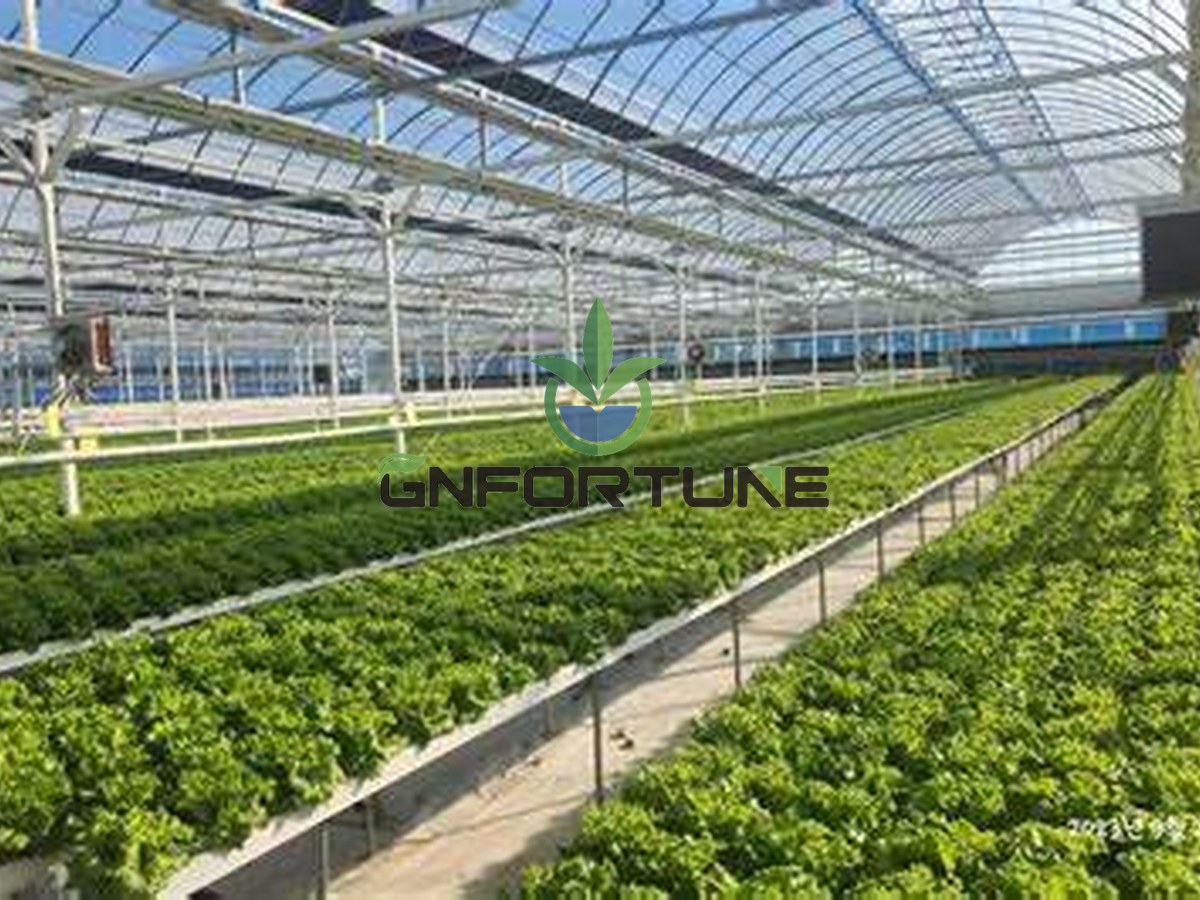
The CO2 sensor is the controller’s only view of reality, and its height decides what reality it reports. A sensor at the ridge measures the reservoir of accumulated gas; a sensor inside the canopy measures what the leaves are breathing. They routinely differ by a wide margin — in still houses with stratification, ridge readings can sit well above canopy readings, and a controller driven by the ridge number will underdose the crop while believing it is generous.
Placement guidance from project work:
- Measure at canopy level, roughly in the upper third of the crop height, in the middle of a representative bay — not beside the door, the burner, or the duct outlet.
- Keep it out of the plume. A sensor downstream of a release point reads the supply concentration, not the house. Move it until the reading is stable and plausible for the crop, not for the jet.
- Two sensors beat one argument. On houses over a few hundred square metres, a second sensor at the far end exposes distribution faults that one sensor averages away.
The general sensor-placement errors that distort readings — draughts, sources, sun — are treated in depth in the guide to sensor placement and where readings go wrong, and CO2 follows the same logic. Calibration and probe care for the other environmental sensors on the same network is described in the sensor calibration article.
Stratification and the Traps That Empty a Dose
CO2 is heavier than air only marginally; in practice it goes where the air goes. That makes stratification the main way dosed gas is lost. The recurring traps:
| Trap | What happens | Fix |
|---|---|---|
| Thermal stratification | Warm ridge air holds the gas above the canopy; leaves see ambient | HAF fans or destratification mixing; release below the ridge, above the crop |
| Open-vent short circuit | Gas released near a windward vent exits within minutes of dosing | Move release points downwind and along rows; tie dosing to vent position |
| Floor pooling | Cold gas sinks under benches and gutters, dosing the floor | Avoid low release points; aim ducts into the canopy |
| End-of-house drift | Long bays accumulate gradient; far end never enriches | Multiple release points or full-length ducts, not one dosing location |
Thermal screens complicate the picture: a closed screen is a ceiling the gas accumulates under, and when the screen opens the whole pocket dumps or escapes. Dosing schedules that ignore screen movement pay for gas the canopy never saw, and the screen behaviour behind this is covered in the guide to thermal screens and night heat retention. Night-time enrichment is rarely worth starting at all — the crop is not photosynthesising.
Verifying That Distribution Actually Works
Verification is cheap and should be done on commissioning and each season after:
- Two-point reading: with dosing active, compare a canopy-level reading at the far end against the sensor near the controller. A persistent gap of more than a small planning tolerance (as a working figure, beyond roughly 50–80 ppm under closed-vent conditions) points at a distribution fault.
- Plume walk: with a portable meter, walk the house during dosing and log readings at consistent points. The map shows dead zones and plume contamination immediately.
- Response check: switch dosing off and watch the decay at both points. A far-end reading that never moved was never enriched, whatever the controller log says.
Record the map and the two-point baseline in the commissioning file. Distribution faults are seasonal — fan schedules, screen settings and vent habits change — and the baseline is what makes next season’s drift visible.
CO2 distribution decides whether enrichment becomes a yield input or an expense line. Ducts that reach the canopy, releases that follow the air loops, and a sensor that measures leaf height are the three details that make the difference — none of them costs much, and all of them are set before the first crop, not after it.
FAQs About CO2 Distribution
How high should CO2 be released above the crop?
Above the canopy and below the ridge, into air already moving toward the crop — typically with overhead ducts showering downward, or burner plumes allowed to spread at the ridge under mixing. Floor-level release pools and wastes gas.
Where should the CO2 sensor be mounted?
At canopy level, in the upper third of crop height, in a representative bay away from doors, plumes and outlets. A ridge-mounted sensor reads the gas reservoir, not what the leaves receive, and underdoses as a result.
Why does the far end of our house never enrich?
Usually one release point serving a long bay, or open-vent short circuiting. Add distribution along the row, tie dosing to vent position, and confirm with a two-point reading at the far end.
Can CO2 dosing run with vents open?
Only with placement tied to airflow: release points downwind and along rows, with the enrichment logic coordinated with vent position. Untied dosing with open vents mostly pays for gas that exits the ridge.
How do we check that distribution is uniform?
Compare canopy-level readings at far and near ends during dosing, walk the house with a portable meter to map dead zones, and verify the far end responds when dosing switches off. Repeat each season as airflow changes.
Related Reading
- CO2 for Hydroponics: How Much Do Plants Need? — The source hardware these placement rules serve
- CO2 for Hydroponics: How Much Do Plants Need — The dosage arithmetic distribution has to deliver
- Sensor Placement: Where Readings Go Wrong — The placement errors every instrument shares
- Greenhouse Ventilation Design: Vents and HAF Fans — The air loops CO2 must ride
- Thermal Screens: Night Heat Retention — The moving ceiling that traps or dumps gas
Next Step: What to Send for a Quotation
CO2 distribution hardware is quoted from the house drawing and the airflow plan, not from gas consumption alone. For an RFQ or project consultation, send: greenhouse dimensions and bay layout; the crop and canopy height; source type (burner, liquid CO2 or ducted supply); existing HAF and vent arrangement; screen type and control; sensor count and mounting plan; whether distribution uniformity testing is wanted at commissioning; delivery schedule; and the budget band. G AND N FORTUNE LIMITED supplies greenhouse and CO2 system components quoted to those parameters as part of complete climate packages.